Drawing printing permission from
A cor Cadesign & Build SPRL(Belgium).
Architectural Solutions:tof-cor@tiscalinet.be
This HP describes PloView of Viewer and Converter which displays, edits,
and converts various graphic files(HP-GL, HP-GL/2, HP RTL, PDF, DXF, DWG,
GERBER, NC-Drill, IGES, SXF, TIFF, JPEG, BITMAP, EMF, PCX, FPX, PNG, GIF).
* PloView function introduction demo video (resolution: 1920 x 1080)
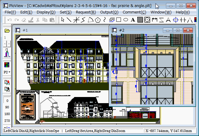
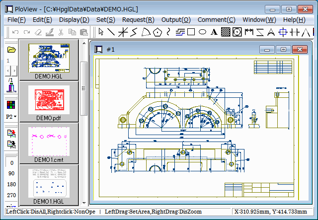
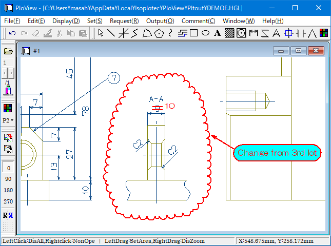
PloView is viewer for viewing drawing of HPGL/Vector/image file.
And, since PloView has about the same powerful input editing function
as 2D-CAD, you can easily create other drawings by diverting design drawings. (1) File: Support to many file formats
Input: HP-GL,HP-GL/2,HP RTL,PDF,DXF,DWG,GERBER,NC-Drill,IGES,SXF,
EMF,TIFF,JPEG,Bitmap,PCX,FPX,GIF,PNG,CMT
Output:HP-GL,HP-GL/2,HP RTL,PDF,DXF,DWG,IGES,SXF,EMF,TIFF,JPEG,Bitmap,
PCX,FPX,GIF,PNG,Printer,Plotter,WMF,PS,EPS,SVG,XPS,PCL,CMT
Black / white and color copy
to clipboard.
In PDF output, add layer attribute to color / page, and annotate
cloud mark. (2) Multi-page file support
- Open multiple files, display page, combine into multi-page file
- Multi-page file divided into different files for each page (3) Display
- High-speed display of vector drawing, and many commands about display
- Color and width change of line, “black and white” / “color” change,
background color change, pen ON/OFF
- Display mode (Copy/Merge/Xor/data) change
- Rotation, mirror, grid displaying
- Thumbnail display
- Multi-page correspondence
- Vector font / TrueType font change of text font (4) Request
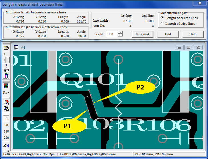
- Measurement function of coordinates, length, area, line width,
and angle
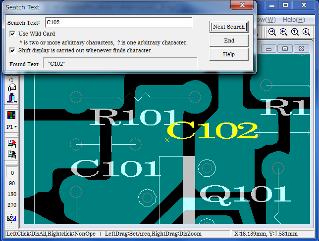
- Search text
- Connected line search, the total line length measurement (5) Edit drawing (Comment function)
* File:
- New create
- Input file of (1)
- Save to file of (1)
* Insert:
Figure kind:
Polyline, Arc, Circle, Horizontal line, Vertical line,
Slanting line,
Opposite side angle line, Regular polygon, Ellipse,
Offset line,
Free curve, Cloud shape line, Spline, Surface, Rectangle,
Long circle,
Text, Bitmap, Macro,
Dimension (Horizontal, Vertical, Parallel, Angle, Radius,
Diameter) Enter coordinates with the key, Insert Same Point, Next Same Point,
Insert-Grid ON/OFF"
* Set:
Layer: 1..20, Set property * Edit:
Setup, Select (individual selecting, rectangular area selecting,
polygon area selecting), Move copy, Delete,
Divide/Delete/Move/RouteChange polyline section,
Delete line in selected area boundary, Trim, Change property,
Change vertex R, Chamfer, Connect Line, Rotate copy,
Scale Up/Down copy, Macro-izing, Macro breakup, ReDo, UnDo * Display, request
Same as (3) (4)
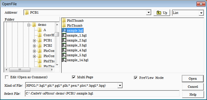
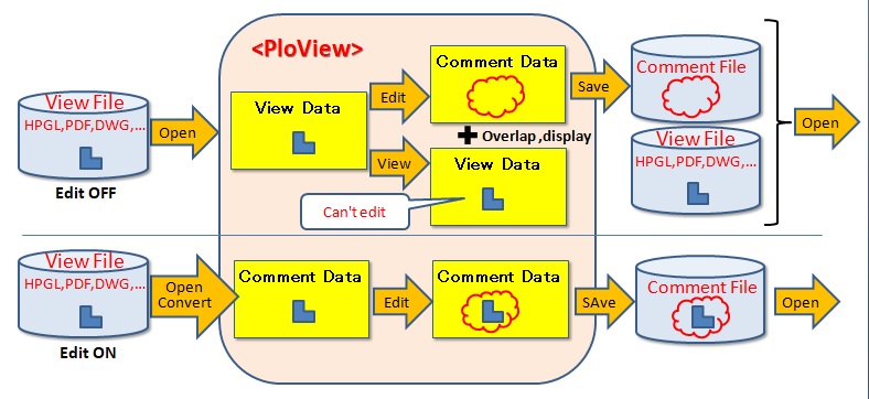
File to open:
(1) View file : file to see
HP-GL, HP-GL/2, HP RTL, PDF, DXF, DWG, GERBER, NC-Drill,
IGES, SXF, EMF, TIFF, JPEG, Bitmap, PCX, FPX, PNG
(2) Comment file : file CMT to edit
Edit
- Check ON
When selected file is view file, it can convert to comment, and
edit.
Don't display view file.
- Check OFF
Open in order to see, when selected file is view file.
In addition, comment can be added to view file in piles.
- Check ON and OFF
When comment file is specified, it opens as a comment and can edit.
PreView mode
When this check mark is applied, it will be opened whenever it selects
file of file list, and will be displayed on the whole screen.
It is convenient to see plural files continuously.
When check mark is removed, it don't open until the Open button is
pushed.
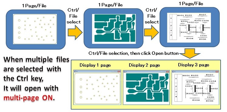
Multi-page
When this check mark is applied and drawing file consists of multi-pages,
it will be divided and read into two or more pages as a multi-page.
When this check mark is removed and drawing file consists of multi-pages,
all the pages will be read into the 1st page in piles.
How to open multiple files simultaneously
Hold down the Ctrl key or Shift key and select the file with the mouse.
The Ctrl key can be selected one file at a time.
The Shift key selects all the files between the first selected file in the file list and the second selected file.
The order in which files are opened is the order in which they are displayed in the "File List" of this dialog.
In the "File List", you can rearrange by combining the combo box in the upper right corner of this dialog with "Report" and clicking the cell at the top of the "File List".
When you press the Ctrl key or Shift key, "MultiPage" turns ON, "Edit (open as comment)" and "Preview Mode" turns OFF.
If you open multiple files in this way, the file will be expanded to the page.
If one file is multi-page, this file will expand to multiple pages.
Example:
File composition to read
1st file: ABC.hgl 2 page structure
2nd file: DEF.hgl 1 page structure
Parent Window Displays the name of the first file in the title.
Child Window Displays the file name of the open page in the title.
Please refer to "Drawing area when reading file of PloView series product" for drawing area(area displayed when issuing display all command)
of the opened file.
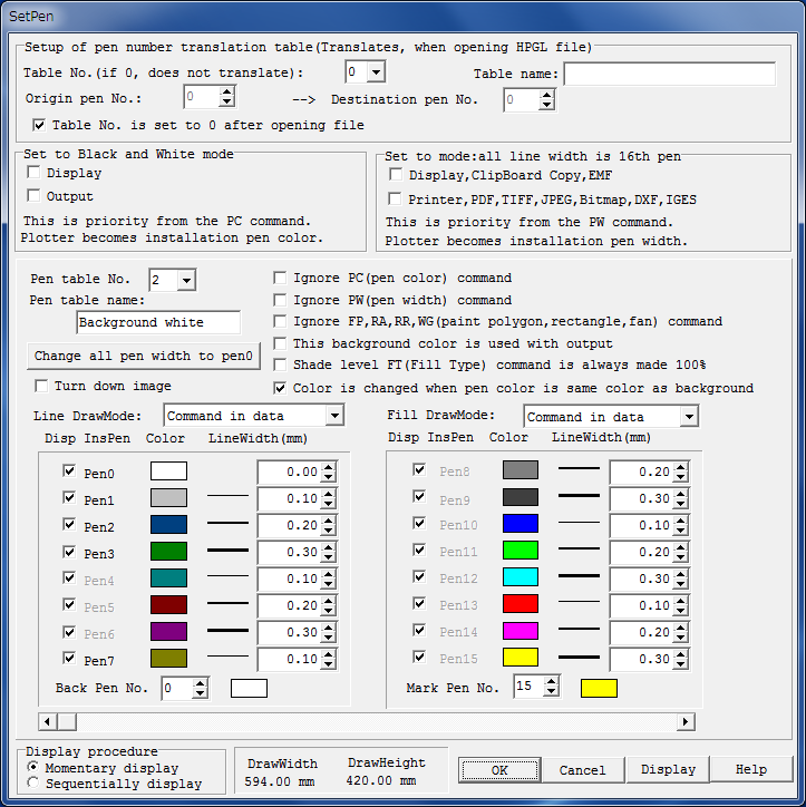
Usually, although displayed with color of pen and line width in drawing
data, it is changeable with setup of pen.
* Input pen
When this pen number is gray display, it is shown that this pen is
not inputted into drawing data, and it is shown in case of bright display
that this pen is inputted into drawing data.
Display of this pen can turn OFF by removing check mark.
* Pen table No.
This item is applied when "Priority 3" is set in "Setup
of foreground color" below.
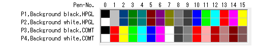
The pen table information has table numbers from 1 to 20, and stores the color and line width for each pen number. The initial color values of the pen table are as follows when the table numbers are 1 to 4 and the pen numbers are 0 to 15.
PenTable-No.1 HPGL color table
screen background color black
PenTable-No.2 HPGL color table
screen background color white
PenTable-No.3 Comment color table screen
background color black
PenTable-No.4 Comment color table screen
background color white
PenTable-No.5-20 not set reference:
For example, the color of the pen table is as follows.
PenTable-No.1,2 PenTable-No.3,4
Color HPGL color table Comment color table
Red Pen-No.13 Pen-No.1
Green Pen-No.11 Pen-No.3
Blue Pen-No.10 Pen-No.5
If there is no PC(pen color) command in the view file(open with edit
off), it will open in the color table of the specified PenTable-No.
Comment files(open with edit on) always open in the comment color table.
PenTable-No.1,2
Use the HPGL color table to display the view file.
The pen number(= color number) of the figure in the comment file opened with Edit turned on does not match the view file of the conversion source.
For example, in the view file, Pen No.13 is displayed as red.
When this is converted to a comment file, it will be displayed in
the same color, so it will be converted to Pen No.1 (= color number 1).
PenTable-No.3,4
Use the comment color table to display the view file.
The pen number(= color number) of the figure in the comment file opened
with Edit turned on matches the view file of the conversion source.
For example, in the view file, Pen No.1 is displayed as red.
When this is converted to a comment file, it will be displayed in
the same color, so it will be converted to Pen No.1(= color number 1).
Use PenTable-No.3,4 (comment color table) if you want to open the
file with edit on and output to the HPGL pen plotter to draw figures with
the same number for input and output.
* Color is changed when pen color is same color as background
When it draws with pen of the same color as background color, picture
will disappear.
When this check mark is checked, and background color and drawing
pen are black, drawing pen will be changed white and will be drawn.
When background color and drwaing pen are except black, set drwaing
pen black and draw it.
When input files are DXF, DWG, and IGES file, recommend check ON
for this.
In the case of GERBER file, recommend check OFF.
Please refer to Subject and solution about color.
* Line DrawMode, Fill DrawMode
Select "Copy" to see by over-writing.
Select "Merge" to see overlap part by color mixing.
Select "Xor", when making not visible place with which
figure has overlapped.
When following command of drawing data, select "Command in data".
* Setup of background color
Screen background color:
It becomes the color of pen No. specified by background pen
No.
Background color at the time of outputs, such as printer, and TIFF,
PDF:
It is usually white. If the check mark "This background
color is used with
output" is attached, it will become the color of pen
No. specified by
background pen No.
* Setup of foreground color
Priority 1:
If it is set as monochrome display mode, it will become black
and white.
Priority 2:
"Ignore PC (pen color) command" check mark is removed,
it will become the
color of PC command of drawing data.
Priority 3 will be applied if there is no PC command in drawing
data.
Priority 3:
It becomes the color set up for every pen.
* Setup of line width
Priority 1:
It is displayed with the line width of No.16 pen when you
sets up to
"Set to mode: all line width is 16th pen".
Priority 2:
"Ignore PW (pen width) command" check mark is removed,
it will become the
line width of PW command of drawing data.
Priority 3 will be applied if there is no PW command in drawing
data.
Priority 3:
It becomes the pen width set up for every pen.
Example:
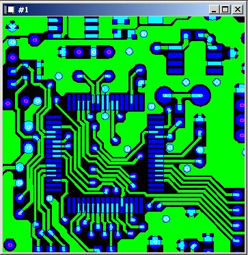
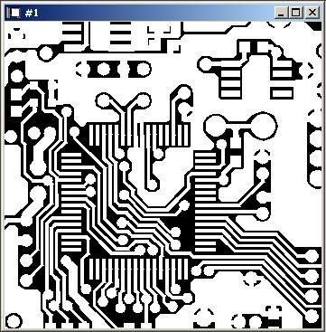
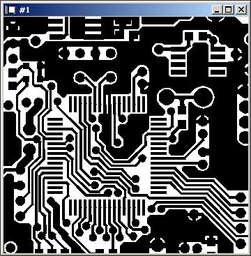
Set to black and white mode OFF and background color as black
Set to black and white mode ON and background color as black
Set to black and white mode ON and background color as white
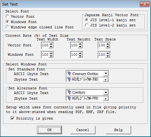
You can set the font size and font typeface of Windows font.
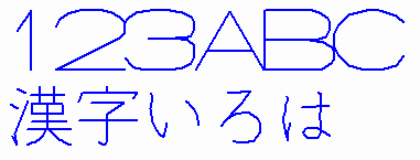
* Vector Font The character shape is drawn with polygonal lines with a fixed line width,
which is quite different from the Windows TrueType font. In general, Vector
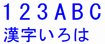
fonts display faster than Windows TrueType fonts. * Windows Font
Displayed with the selected Windows TrueType font.
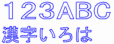
* Windows Font Closed Line Character

            Displays the selected Windows TrueType font as a closed-line character
            without filling it. Use it when you want to draw characters cut with a
            cutting plotter.
You can select the unit system of coordinates and dimensions to use from the following.
* Millimeter mm
* Centimeter cm
* Meter m
* Inch in
* Foot ft
* Yard yd
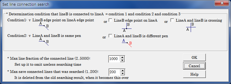
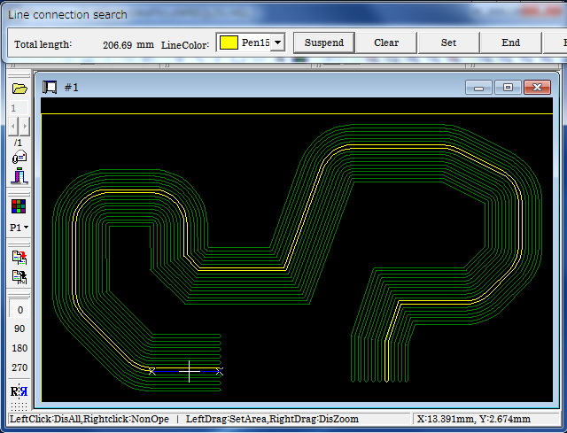
Line connected with specified line of vector drawing data can be searched.
Search results are displayed on screen as the specified color. Since these
search results are memorized temporarily, it will disappear, if it performs
clearing search results or ending this program, or it searches connection
of the next line, or it opens another file etc. If it is while having memorized,
displaying, printer output, PDF output, DXF output, and clipboard copy
can be performed for search results. The total line segment length of connected
line who searched is displayed. Area is displayed that connected line has
closed.
Search condition setup
Move the mouse cursor closer to the line, the line will be recognized.
If mouse button is clicked here, continuous line is searched, and color
is changed and displayed as shown next figure.
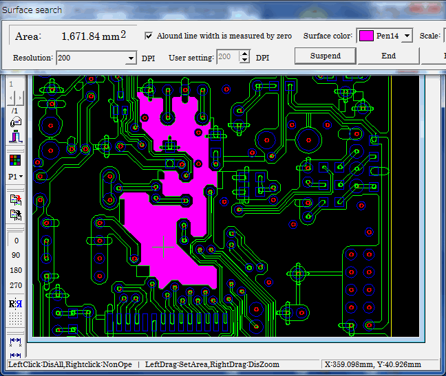
Surface can be searched when you click closed line with the mouse left
button. Surface is smeared away and search results are displayed on screen
as color specified in "Surface color". Area of surface searched
in dialog is displayed.
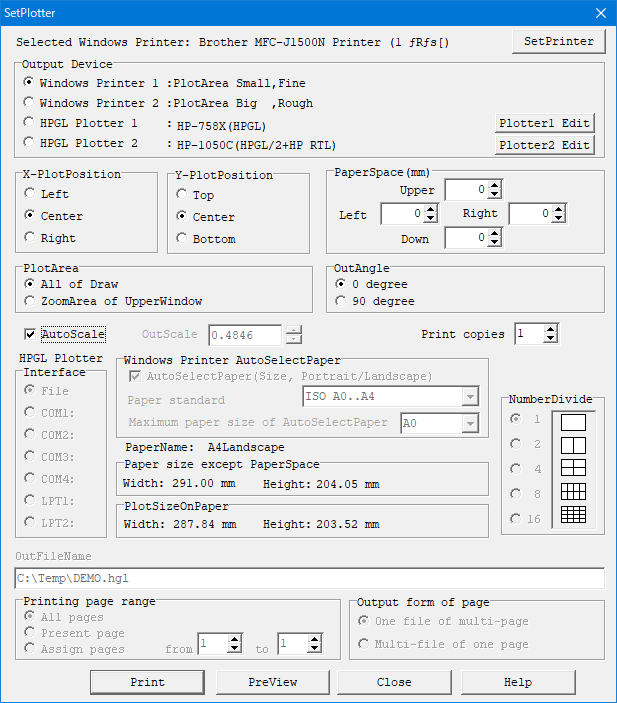
It can output to Windows printer or HPGL plotter.
You can preview before output.
* OutScale
Output on the scale specified here.
If the paper is large with respect to the drawing area, a margin will appear, and if the paper is small, the drawing will be clipped.
* AutoScale
When this check mark is attached, the output scale is automatically set
so that the drawing area fills the paper area excluding the paper margin.
At this time, "OutScale" can not be set.
* AutoSelectPaper(Size, Portrait/Landscape)
Specify the paper standard loaded in the printer in "Paper standard" from the following.
ISO A0 to A4
ISO B0 to B5
JIS B0 to B5
ANSI A to E
ARCH A to E, E1
This function is effective when "AutoScale" check mark is not
attached. The paper size according to the output drawing size is automatically
determined from the standard paper size. Also, the paper direction is automatically
determined Portrait and Landscape. If the printer does not support the
paper size, or if the printer can not change the paper orientation, do
not select its size or direction. When the output drawing size exceeds
the maximum paper size that can be selected, select the maximum paper and
automatically adjust the output scale so that the drawing size matches
that paper size.
* HPGL file output
When you select a file as an output destination in the plotter output, you can obtain the following HP-GL file.
· HP-GL file with scale, angle, mirror ON/OFF changed
· HP-GL file of expanded area
· HP-GL file combining comments and HP-GL files
· Minimum unit of coordinate of constituent points of figure
The minimum movement unit of the initial value HPGL plotter is 0.025mm
for both XY, and this is taken as one unit and expressed as an integer.
However, you can change the minimum movement unit with the
following
settings.
Press the Plotter1 Edit or Plotter2 Edit button in
the SetPlotter Dialog.
Correct the next value (initial value 40.0) on the
displayed screen
and save it.
#2 PlotterUnits by 1mm(Step Count)
40.0
For example, if the minimum movement unit is
0.001mm, set it to 1000.0.
· The HP-GL specification of data can be selected from the following
three
types.
HP-GL (low function vector data)
HP-GL/2 (high function vector data)
HP-GL/2 + HP RTL (high function vector data + raster
data)
· Convert characters to line segments ON/OFF
· Convert circular arc to polygon ON/OFF
· Convert fill to line segment ON/OFF
· Moving the origin position of HPGL
(same as lower left of drawing area / drawing origin)
· Get one HPGL file combining pages of multiple files(1 page file,
and
multi page file).
Alternatively, get the HPGL file by dividing each page into
separate files.
* Output form of page
It can be used when "HPGL Plotter 1" or "HPGL Plotter 2" is selected for "Output Device".
There are two output forms as follows.
(1) One file of multi-page
Combine each page of the opened file into one multi-page
HPGL file.
(2) Multi-file of one page
Divide each page of the opened file into separate HPGL files
(one page).
If there are multiple pages, the page number of _001 to _999
is appended
at the end of the output file name.
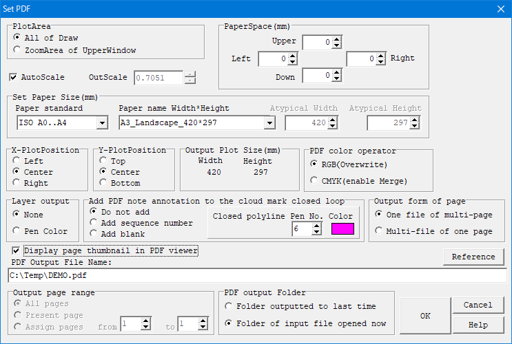
It can output to PDF, DXF, DWG, TIFF, JPEG, Bitmap, PCX, FPX, GIF, PNG,
IGES, SXF, WMF, PS, EPS, SVG, XPS, PCL and EMF file.
Overprint is supported with PDF output.
Output Setting Dialog:
the case of PDF output
Various output
setting items (* Mark)
PDF
TIFF
DXF
DWG
JPEG
BMP
GIF
PNG
PCX
FPX
IGES
EMF
WMF
PS
EPS
SVG
XPS
PCL
SXF
(P21)
(SFC)
Plot area (AllArea/ZoomArea)
*
*
*
*
*
*
*
*
All
Out scale
*
*
*
*
*
*
*
*
Auto scale
*
*
*
*
*
Paper size (Standard,Width,Height)
*
*
*
*
*
Auto paper select
*
*
*
*
*
Paper margin
*
*
*
*
*
Position of drawing on paper
*
*
*
*
*
Output page range (Note 1)
*
*
*
*
*
*
*
*
*
Output file name
*
*
*
*
*
*
*
*
*
Color operator (RGB/CMYK)
*
*
Layer output
*
Add PDF note annotation to
the cloud mark closed loop
*
Output form of page
*
*
Diaplay page thumbnail in
PDF Viewer
*
Resolution
*
*
*
Color (BW/16/256/16million)
*
*
*
TIFF-Type (Note 2)
*
AutoCAD Version (GX-5/2002)
*
JPEG Compression ratio
*
Convert HPGL-Pen to IGES-Pen
*
SXF Version (2.0/3.0/3.1)
*
Note 1: Output page range ... All pages/Plesent page/Assign
page
Note 2: TIFF-Type ··· Un-compressing/CCITT RLE/GROUP3 1D/GROUP3
2D/Group 4/PACKBITS/LZW
* AutoScale
When this check mark is applied, OutScale will be automatically set
up so that drawing area may fill paper area except PaperSpace.
It becomes impossible to set up "OutScale" at this time.
* OutScale
When check mark of "AutoScale" is OFF, it is effective,
and specify scale factor to output in 0.01-100.0.
Since case where output drawing size exceeds paper size will occur
when this scale factor becomes large, cautions are required.
In this case, message of "* Over Size !" is displayed on
Output Plot Size field.
* Set Paper Size
Specify the paper size to be output.
In the "Paper standard", specify the paper standard from
the following.
ISO A0 to A4
ISO B0 to B5
JIS B0 to B5
ANSI A - E
ARCH A to E, E1
You can select fixed form paper (paper name, paper size, Portrait/Landscape)
from the series at "Paper name width * height".
By specifying "Atypical size", you can specify the width and height of the paper in the "Atypical Width" and "Atypical Height" fields.
When "Drawing area + margin" is specified, the area containing
"PaperSpace" is the paper size in the drawing area of the specified
"OutScale".
When "AutoPaperSelect" is specified, the optimum paper
size is automatically selected from the area containing the "PaperApace"
in the drawing area of the specified "OutScale", and Portrait/Landscape
is also automatically selected.
* Output form of page
There are two output forms as follows.
(1) One file of multi-page
Combine each page of the opened file into one multi-page
output file.
(2) Multi-file of one page
Divide each page of the opened file into separate output
files (one page).
If there are multiple pages, the page number of _001 to _999
is appended
at the end of the output file name.
File page division, page combination
* Support overprint with PDF output
When "Line DrawMode" and "Fill DrawMode" are
specified as "Merge" with Set-Pen menu and "CMYK" is
selected for "PDF color operator" at the time of PDF output,
overlapping figure will display by mixed color.
In addition, in order to confirm mixed color by AcrobatReader, please
start AcrobatReader, select edit-configuration menu, select "page
display" of classification, and set "Use overprint preview"
into "automatic" or "always".
Display PDF data outputted by overprint OFF by AcrobatReader.
Display PDF data outputted by overprint ON by AcrobatReader.
... The bottom of the overlapping figure is displayed.
Note1 The image will not overprint and will be displayed as overlay.
Note2 If the colors(regardless of density) of the superimposed figures are similar, they will not be mixed colors. White shapes are ignored. This problem is due to the PDF overprint specification.
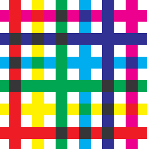
Sample PDF file ... TestPdfOverPrint.pdf Open this file with AcrobatReader and check the color of the overlapping part. Top figure Vertical line Bottom figure Horizontal line The combinations of red-yellow, red-magenta, green-cyan, green-yellow, blue-cyan, blue-magenta are not mixed colors. Enlarged view of TestPdfOverPrint.pdf
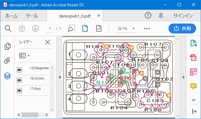
* PDF output layer function
When outputting the layer, the attribute of the layer is included in the figure of the PDF file, and the display can be turned ON / OFF by the layer in the PDF viewer.
(1) None
Layers are not output.
(2) Pen Color
Roll the pen color to the color shown below and output it
as the layer.
(3) Page
When the "Multi page" check in the "Open File" dialog is OFF, the page
is output as the layer number.
The maximum layer number is 20, and the pages after page
20 are layer
number 20.
* Add PDF note annotation to the cloud mark closed loop
When you output the note annotation, the note annotation is included in the PDF file, you can check the note annotation with the PDF viewer, and enter change article etc in the note annotation.
(1) Do not add
Do not add PDF note annotation.
(2) Add sequence number
If there is data of the following condition in the data,
the PDF note
annotation of the sequence number starting from 1 is automatically
added to
that position.
The sequence number is the order of entry of each view file
→ comment.
(3) Add blank
If there is data of the following condition in the data,
blank PDF note
annotation is automatically added to that position.
· Additional conditions:
View file
The same as "Closed polyline Pen No. Color", Polyline
turned to clockwise
closed loop
Comment file
The same as "Closed polyline Pen No. Color", Cloud mark polyline that turned
to clockwise closed loop
· Position of PDF note annotation:
It is the upper right corner of the cloud mark.
Display PDF output layer and note annotation with Acrobat
Reader
(1) Drawing comparison of multi-page PDF file
With PloView and PloComp you can compare the same pages in two multi-page
PDF files and get one multi-page PDF file with change area (cloud mark).
Settings other than those set here for PloView and PloComp are in the installed
state.
Delete the following folder to put the setting values in the installed state.
PloView: C:\Users\<username>\AppData\Local\Isoplotec\PloView
PloComp: C:\Users\<username>\AppData\Local\Isoplotec\PloComp
Note: <username> is your Windows account name
Step-1 · · · Divide by PloView
Launch PloView
Select "File" "Open" menu
"Edit" to "OFF"
"Multi page" to "ON"
Open multi-page PDF file 1
Select "Output" "Printer, Plotter Output" menu
"Output device" as "HPGL Plotter 2"
Press "Plotter2 Edit" button
"HPGL Origin" as "2"
"OutScale" as "1.0"
"Output form of page" as "Multi-file of one
page"
Press "Print" button
Get one page HPGL file 1.
Do the same operation for multi-page PDF file 2.
Step 2 ... Drawing comparison with PloComp
Launch PloComp
Open the file of the same page of 1 and 2 files output in Step-1.
"Drawing Comparison" in "Request" "Change
Area" Menu
Select "Output" "Printer, Plotter Output" menu
Output 1 page HPGL file under the same conditions as Step
1
Perform the same operation for all pages.
Step-3 ... Combine files with PloView
Launch PloView
Select "File" "Open" menu
Hold down the Ctrl key or Shift key and select all the files
that you output in step 2 with the mouse.
Select "Output" "PDF" menu
"OutScale" as "1.0"
"Paper name" as "drawing area + margin"
"Layer output" to "Pen Color"
"Add PDF note annotation to cloud mark closed loop"
as "Add sequence number"
"Output form of page" as "One file of multi-page"
"PDF color operator" as "CMYK (enable Merge)"
output
Drawing comparison
of multi-page PDF file
Note: The input and output files are PDF files here, but the same can be
done for HPGL files and TIFF files that can be multi-paged.
Reference: There is "PloCVAuto" that can automatically compare drawings of multi-page files.
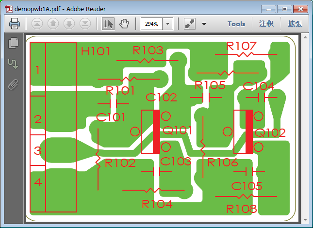
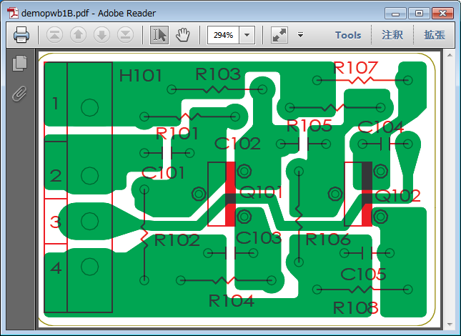
(2) Make a drawing composed of a plurality of files into a multi-page PDF
file
It is an example of overlapping multiple drawings into one product like
the printed board.
Open multiple drawings in PloView and make it one multi page file such as HPGL, PDF etc
When you open this file you can see overlapping in PloView and you can use the layer function when outputting to PDF.
Step-1 ... File combination
Launch PloView
Select the "File" "Open" menu, hold down the
Ctrl key or Shift key and select all files with the mouse.
You can see each file by page feed.
Select "output" "plotter, printer output" menu
"Output device" as "HPGL Plotter 2"
Press "Edit Plotter 2" button
"HPGL Origin" as "2"
"Output scale" is set to "1.0"
"Output form of page" as "Multi-page 1 file"
Press "Print" button
Get multi-page HPGL file
Step-2 · · · PDF output
Launch PloView
Select "File" "Open" menu
"Multi page" is set to "OFF"
Open the file output in Step-1
The pages are displayed overlapping.
Select "Output" "PDF output" menu
"Output scale" is set to "1.0"
"Paper name" as "drawing area + margin"
"Layer output" to "pen color"
"Output form of page" as "Multi-page 1 file"
"PDF color operator" as "CMYK (enable Merge)"
output
PloView has about the same powerful drawing input editing function
as 2D-CAD as a comment function.
When this function is used, postscript will be possible for existing
drawing. And, existing drawing is diverted and another drawing can be easily
created by performing addition, deletion, movement and change etc. for
figure.
Refer to the "Drawing editor of PloView and PloComp" for details of drawing edit function.
* File:
- New create
- The next file can be read and edited.
View file:
Page number of file links to layer number,
and it is read.
HP-GL, HP-GL/2, HP RTL, PDF, DXF, DWG, GERBER, NC-Drill, IGES,
SXF, EMF, TIFF, JPEG, Bitmap, PCX, FPX, GIF,
PNG
Comment file:
CMT
- Edit result can be saved in piles with view file at the next file.
HP-GL, HP-GL/2, HP RTL, PDF, DXF, DWG,IGES, EMF, TIFF,
JPEG,
Bitmap, PCX, FPX, GIF, PNG, printer, plotter, WMF,
PS, EPS,
SVG, XPS, PCL, CMT (CMT cannot be saved in piles with
view file)
Black / white and color copy to clipboard. * Insert:
Figure kind:
Polyline, Arc, Circle, Horizontal line, Vertical line, Slanting
line,
Opposite side angle line, Regular polygon, Ellipse, Offset
line,
Free curve, Cloud shape line, Spline, Surface, Rectangle,
Long circle,
Text, Bitmap, Macro,
Dimension (Horizontal, Vertical, Parallel, Angle, Radius,
Diameter)
Insert Coodinates at Key, Insert Same Point, Next Same Point,
Insert-Grid ON/OFF" * Set:
Layer: 1..20, Set property * Edit:
Select (individual, rectangular area, polygon area selecting),
Move copy, Delete, Divide/Delete/Move/RouteChange polyline section,
Delete line in selected area boundary, Trim, Change property,
Change vertex R, Chamfer, Connect Line, Rotate copy, Scale Up/Down
copy,
Macro-izing, Macro breakup, ReDo, UnDo * Display, Request
1. PloView Ver.12.0 Operating conditions
Personal computer of Intel compatible CPU mounting
- Empty capacity of memory: 2GB or more
- Empty capacity of hard disk drive: 2GB or more
- Screen resolution: 1024 dots x 768 dots Above
- OS: Windows 7, 8, 10 and 11 32Bit, 64Bit
- It is necessary to install some printer drivers.
Printer driver of high resolution is required to read PDF file.
- It is necessary to install free software "ODA File Converter" at input and output of DWG file.
- When outputting EMF file, it is necessary to set the following settings
of Windows to the initial values.
"Start" "Settings" "System" "Display"
"Scale and layout" 100% (initial value)
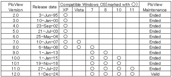
2. Supported OS and maintenance for each PloView version
1. Trial
Please download product from this HP. Since product is compressed
into ZIP file, please extract it with suitable thawing software. There
is a file called Readme.txt in the decompressed file, so read the product
overview, installation method, uninstallation method, license agreement,
licensing fee, license cancellation, protection release, inquiries, and
version upgrade history. And since a file called SetupPloViewE.exe is in
extracted inside, it is installable if it double-clicks by Explorer. Opening
to the public on HP serves both as trial and object for formal. All the
function usage can be carried out free for 30 days from installation for
trial. If 30 day will pass and password will not be entered, protection
starts and product stops working. Please order the formal version, when
you use more.
2. Order of formal version
It can pay with PayPal or credit card with the next button.
Please refer to Readme.txt file to carry out bank transfer.
Please send the next "order sheet" to e-mail address described
at the last of this HP.
Order sheet
1. Soft name: PloView (English)
2. Soft version no.: 12.0
3. Order quantity: 1
4. Company name:
5. Offer person name:
6. Offer person E-mail ID:
7. Charge payment day:
8. Charge payment amount:
3.Sending of password
The copyright holder will email the password when payment of the
licensing fee has been confirmed.
4.Release of lock
In order to enter password, when starting PloView.exe, it is necessary
to carry out mouse right-click, to take out pop up menu, and to select
"Run as administrator". Execute PloView and display 'Version
Information' dialog box with the menu 'Help'-'Version Information' and
input the password.
5.OS exchange, or exchange of installation personal computer
Even if you replace exchange of OS, or installation personal computer,
given password can release lock.
However, the number which can install product in personal computer
simultaneously is not exceeding ordered number.
6.Revision up (rise of the 2nd place of decimal point of version number)
Revision up is free of charge.
Software of new revision is downloaded and reinstalled from the Internet
HP.
Previous password is effective.
Ver.10.04 August 12, 2015
(1) SXF output functions were added.
(2) Defect of SXF input was repaired.
(3) With DXF output, when there existed image, it repaired abnormal having
outputted.
(4) Text of Vector font repaired fault which becomes dotted line and chained
line sometimes with DXF and IGES output.
Ver.10.04 September 15, 2015
(5) It supported to Windows10.
Ver.10.04 November 17, 2015
(6) Abnormality display has been improved for arc of very small angle.
(7) In PDF output etc., polygon-ized accuracy of very small circle painting
out was raised.
Ver.10.04 November 20, 2015
(8) It enabled it to set up judgment angle of very small arc or circle
by "Set"-"Input file"-"Circle and arc judging
angle".
Ver.10.04 March 16, 2016
(9) Function when "#2 PlotterUnits by 1mm(Step Count)" was changed
with Plotter Edit button of HPGL Plotter output was changed.
(10) In the condition that file in which comment Bitmap exists is rotated
and displayed, when HPGL Plotter output was carried out, it repaired displaying
Bitmap on abnormal position.
Ver.10.04 April 3, 2016
(11) With HPGL Plotter output, it repaired that Up and Down length of dotted
line, dashed line, and chained line of comment was abnormal.
Ver.10.04 July 19, 2016
(12) Problem when file with comment created by PloView before Ver.9.0 is
opened was repaired.
Ver.10.04 July 25, 2016
(13) Defect of LA (line attribute) command in case line end and joint shape
are except being round was repaired.
(14) "Initial of Line End Shape" of "Set-Line property"
dialog was changed into "Shape of line end and joint".
Ver.10.04 September 15, 2016
(15) Depending on PDF creation application, PDF version information may
not match notation and entity. When such a PDF file was read, it was not
able to read (error code=10000).
It enabled it to read this.
Ver.10.04 September 23, 2016
(16) When HPGL file was opened in the state of ON of "edit",
it repaired that painting-out processing became abnormal.
Ver.10.04 October 1, 2016
(17) When another command (point out menu or icon) was issued without pressing
Enter key (end is illustrated) during comment input, it repaired that display
was abnormal.
(18) Insert comment into file which is not entered. And it outputs without
displaying. Then, there was problem to which comment is not outputted.
This was repaired.
(19) After output, input comment without displaying. Then, there was problem
to which color of dragging or rubber band of figure while input becomes
strange. This was repaired.
Ver.10.04 November 6, 2016
(20) Display command can be issued while comment input.
Ver.10.04 December 20, 2016
(21) When Bitmap was in Macro of comment, other figures were displayed
under Bitmap and had disappeared. This was improved so that other figures
might be displayed on Bitmap.
(22) When various outputs were performed after changing comment drawing
size, it had not become drawing size after change. This defect was repaired.
(23) When Macro input of comment was carried out after carrying out various
setup, setup after change was not being reflected. This was repaired.
(24) It was made to reflect "Ignore PC command" of SetPen in
Macro input of comment.
(25) When output drawing size is larger than paper size by preview of Printer-Plotter
output, drawing of the right,left,upper and lower position was abnormal.
This was repaired.
Ver.10.04 December 23, 2016
(26) File of only comment data was opened, and when the number of plotter
units set except 40 and carried out HPGL Plotter output, it repaired that
output HPGL data became abnormal.
Ver.10.04 January 3, 2017
(27) PayPal fee about licensing fee remittance which user had paid was
eliminated.
Ver.10.04 January 9, 2017
(28) When evaluation period goes out, or when uninstalling, function which
fills in evaluation result and carries out e mail transmission was added.
Ver.10.05 February 20, 2017
(1) At the time of comment input, function in which it can input after
displaying comment property set Dialog and setting property was added.
ON/OFF of this function can be performed by comment property set Dialog.
(2) It enabled it to issue display command by key while comment input.
Ver.10.05 May 10, 2017
(3) It was ignored when there existed Bitmap which black and white reversed
in PDF and EMF input, and it repaired becoming whole surface black. Ver.10.05 September 27, 2017
(4) Display of FT command of HPGL was improved. Ver.10.05 January 29, 2018
(5) Fixed abnormally when opening some abnormal files.
Ver.10.06 March 27, 2018
(1) The paper standard (ISO A0-A4, ISO B0-B5, JIS B0-B5, ANSI A-E, ARCH
A-E,E1) can be set by specifying the paper size of the printer, PDF, TIFF,
Bitmap, JPEG, GIF, PNG, PCX, FPX output Dailog.
(2) At "File" - "Create new comment" command, or "Set"
- "Comment draw area" command, drawing size can be selected from
next paper standard paper size.
ISO A0-A4, ISO B0-B5, JIS B0-B5, ANSI A-E, ARCH A-E,E1
(3) In the case of automatic paper selection with printer output, when
the output drawing size exceeds the maximum paper size that can be selected,
the largest paper is selected and the output scale is automatically adjusted
so that the drawing size matches the paper size.
(4) When selecting automatic paper for output (PDF, TIFF, Bitmap, JPEG,
GIF, PNG, PCX, FPX), change the smallest paper selection order as follows.
Conventional
A4 landscape → A4 portrait → A3 landscape → A3 portrait
New
A4 portrait → A4 landscape → A3 landscape → A3 portrait
(5) The paper size was displayed in the preview window toolbar when previewing
with printer output.
(6) By double clicking the status bar of the main window, XY coordinates
of HPGL unit (0.025 mm is 1 HPGL unit) are displayed in addition to ordinary
XY coordinates.
(7) When opening a multi-page drawing with different drawing size and previewing
the plotter and printer output, we corrected to display abnormal.
(8) Fixed the problem that character position shifted under extremely rare
conditions.
Condition:
When characters are drawn with multiple LB (label command) without pen
movement instruction after LO (label origin command) other than initial
value
(9) Under the following conditions, we corrected the fault that black and
white color selection was displayed incorrectly.
Set to black and white
Data that draws figures while changing colors with PC (pen color designation)
command
(10) Fixed an obstacle in which filled figures are not displayed with EMF
output.
(11) When the special output version of PloView of automatic output is
activated on the command line and the output type changes, the problem
that the output condition becomes indefinite unless the same output is
made in the dialog mode beforehand was fixed. Ver.10.06 May 04, 2018
(12) Improved reading accuracy of PDF files.
PDF reading scale correction is automatically set during installation.
PDF reading scale correction X, Y can be set in the input
file setting.
We prepared a button which can automatically set PDF reading
scale correction X, Y in input file setting.
PDF reading scale correction can be set automatically on the
command line.
(13) Changed the output scale in File - Convert PDF file menu as follows.
Applied to PS, EPS, XPS, HGL, PCL -> Aplide to PS, EPS,
XPS, PCL
Note: This scale also applies when opening PDF ->
HGL applies PDF reading scale correction
of input file setting Dialog
Conventionally, the same value was used for Convert PDF file
and PDF open, but this time separate memories are memorized. Ver. 10.06 May 08, 2018
(14) Fixed the problem that the mirror does not be applied the hatching
angle when DXF, SXF was output with mirror ON.
(15) The accuracy of PDF output was improved. Ver.10.06 May 24, 2018
(16) Improvement of fine arc filling accuracy with various outputs. Ver.10.06 Jun 11, 2018
(17) When the resolution was over 45 degrees with CI (circle drawing) command
of HPGL, it was drawing with octagon. We changed it to draw with a triangle
when the resolution is 120 degrees or more.
Ver.10.06 June 29, 2018
(18) With "Length measurement between points" and "Length
measurement between lines", when the dimension measurement Dialog
was displayed, it was pressed without pressing the "Start" button.
Also, while designating measurement points, display commands other than
mouse clicks can be issued.
(19) The following obstacles to "Length measurement between points"
and "Length measurement between lines" were improved.
While measuring, press the end button after displaying the zoom with the
middle mouse button, and drag display with the middle mouse button, the
dimension measurement Dialog is displayed.
Ver.10.06 July 19, 2018
(20) Improve not to flicker display when scroll bar is moved with drag mode ON.
(21) When set to display the scroll bar, the problem that the zoom display area and the scroll bar display area do not match partially was fixed.
(22) We adjusted the size of WindowsFont with PDF output.
Ver.10.06 July 31, 2018
(23) We adjusted the size of WindowsFont with PDF output. Ver.10.06 August 6, 2018
(24) We adjusted the size of WindowsFont by screen display and image file
output. Ver.10.06 August 10, 2018
(25) The initial color values of pen table No. 3 and 4 are matched with
the color table of the comment file. When using this table, when converting
the view file to the comment file, the pen number of the figure of the
comment file becomes the same as the view file. Ver.10.06 August 16, 2018
(26) Fixed an obstacle that did not display the text color found in "Request-Text"
as mark pen color.
(27) When changing the pen table No., the mark pen number is changed so
that the mark pen color does not change. Ver.10.06 October 23, 2018
(28) Kanji of HPGL specification is to switch to kanji mode and to use
JIS code by LB (Label) command. However, there is data that uses ShiftJIS
code in the case of not switching to Kanji mode (1 Byte mode).
Therefore, even in such a case, we improved to display Kanji.
(29) When Text size correction was set to something other than 100% with
Set-Text, it did not work correction value or position of Text. We improved
this.
(30) If Text is on the boundary of the drawing size, influence the drawing
area. Conventionally, when "Text size correction" is set to a
value other than 100% in Set-Text, when opening a file, Text area was calculated
with standard size. This was changed to the corrected size.
(31) In case of combination of DV (horizontal writing, vertical writing
character) instruction and LO (designation of left alignment, right alignment,
centering of character string) instruction, there was a case where character
misalignment occurred. We fixed this.
(32) When the Slant angle of Text was other than 0 degree in PDF output,
it displayed abnormally. We fixed this.
(33) Fixed a problem that caused a system error if the file extension was
not registered when specifying the file name to be opened on the command
line.
・ ・ ・ PloViewAuto compatible automatic output PloView function for special
specification
(34) When selecting the automatic paper selection for various kinds of
output and the drawing size of the opened file coincides with the standard
paper size, the one larger size was selected. We fixed this.
(35) Some menu shortcut keys did not work. We fixed this.
(36) When inputs DXF file, clockwise circular data was skipped. We fixed
this.
(37) It was not corresponded with DXF file input when Text width and Text
space were minus (mirror display). Corresponding to this.
(38) Text size at PDF input was adjusted.
Ver.10.10 November 19, 2018
(1) A function to open multiple files at the same time and see by page
feed was added.
To open multiple files, hold down the Ctrl or Shift key and select the
file in the Open dialog.
The order in which files are opened will be the sorted order in the file
open dialog.
Parent Window Displays the name of the first file in the title.
Child Window Displays the file name of the open page in the title.
(2) The function to combine multiple files into one multi-page HPGL, PDF,
TIFF, SXF file was added.
(3) One file consisting of a plurality of pages is stored as a separate
file (HPGL, PDF, TIFF, DXF, DWG, IGES, SXF, Bitmap etc.).
A page number ranging from _001 to _999 is appended at the end of the file
name.
(4) For automatic output special specification version, you can use wildcard
(*. Hgl) for input file name when launching PloView on the command line.
This allows multiple files to be read at the same time.
The order of opening files is alphabetical order of file names.
(5) When multiple files are opened at the same time, [Multi-page file name]
is displayed on the "Request-Input file attribute" menu.
(6) Layer function added in PDF output.
Layer attribute is added for pen color or page when multi page is off.
(7) Added a function to attach PDF notes annotation to cloud mark closed
loop with PDF output. Ver.10.10 December 04, 2018
(8) When selecting the "File" "Create new comment"
menu, the problem that the previously opened file remains is fixed. Ver.10.10 January 23, 2019
(9) The following functions were upgraded by drastically updating the PDF
reading module.
* Traditionally, when reading PDF files edited with PDF editing tools such as Acrobat, edited figures were not displayed. We made it to display.
* Text reading processing was adjusted.
* The clipping process was adjusted.
(10) Processing speed has been greatly improved when multiple file conversion
processing is performed at once for the automatic output special specification
version.
It is realized by newly preparing the next command line.
PloView.exe /z "batch file name"
The batch file is a file conversion process of one line at a time, describing
the conventional command line parameters, and this is described in plural
lines.
(11) When character width or character height is minus in reading EMF file,
it was not displayed with mirror-on. We tried to display with mirror-on.
(12) Fixed an error that caused automatic scale correction of PDF file
setting by selecting set - input file menu.
(13) When opening a file with edit ON, the window in the surface was changed
from filling to alternate filling.
(14) At the time of EMF output, the character width sometimes became abnormal
depending on the situation. We fixed this.
(15) When the origin of Bitmap data is outside the drawing area, the position
of the Bitmap is displayed displaced at Plotter output. We fixed this.
(16) We modified the garbled character by conditions in HPGL file output.
(17) An error occurred when the width of the drawing size or the height
was zero in the image file output. We fixed this.
(18) In DXF, DWG output, polyline error sometimes occurred. We fixed this. Ver.10.10 February 02 day of 2019
(19) Fixed a problem that an error occurs although files are created by
PDF to XPS conversion.
(20) Fixed a problem that PCL conversion from PDF can not be done. Ver.10.10 March 06, 2019
(21) Added "Display page thumbnail in PDF viewer" function in PDF output.
(22) Output "Output page range" as "Prezent page" with various outputs.
After that, we fixed the problem of outputting present page when outputting
with "Assign Pages". Ver.10.10 April 26, 2019
(23) Since the HPGL file has no drawing area information, the maximum area
of figure is used as the drawing area. The "Set""Input File"
menu now allows you to select the method for determining the drawing size
of the HPGL file from the following.
* Figure maximum area
* PS (PlotSize) instruction area.
Maximum area of figure without PS instruction.
* IW (Input Winow) instruction area.
Maximum area of figure without IW instruction.
* IP (ScalePoint) instruction area.
Maximum area of figure without IP instruction.
* Automatic (PS → IW → IP → maximum figure)
In addition, setting whether to include the origin in the drawing size.
(24) PloView drawing area (Dis-All area) when reading DXF / DWG file can be selected from figure maximum area or drawing size of DXF / DGW file. The PloView drawing area when reading SXF file is the drawing size of the SXF file.
(25) The drawing area of output file was made the same as the PloView drawing
area in DXF and SXF file output.
(26) Information indicating drawing area is included in data in HPGL file
output.
When this HPGL file is read by PloView, it is reflected in the drawing
area (whole display area) of PloView. Ver.10.10 May 07, 2019
(27) It was corrected that an error occurs when opening a compressed file
according to conditions. Ver.10.10 Jun 01, 2019
(28) Fixed the problem of abnormal display when there are multiple Splines
according to the condition in DXF file input.
(29) Fixed the problem that the surface becomes abnormal display according
to the condition by PDF file input. Ver.10.10 June 26, 2019
(30) When layer output was set to pen color in PDF output, it was corrected
that there was a case where the pen color which was not used was output
as a layer. Ver.10.10 July 04, 2019
(31) Fixed the problem that the background is white and the figure in which
the MC instruction of HPGL data is Merge is not displayed.
Ver.10.11 July 17, 2019
(1) A mode was added to set HPGL Pen No. to IGES layer No. in IGES output. Ver.10.11 August 20, 2019
(2) Improved that the layer attribute of comment data was not output when
"Layer output" was set for PDF output.
(3) DXF output when opening a file with "Multi Page" ON sometimes
lacked the comment layer attribute. This has been improved.
(4) The picture layer name in the DXF output help was modified.
(5) Improved so that input pen information is not displayed in SetPen Dialog
and Request-Pen Dialog when opened with "Edit" ON. Ver.10.11 Oct 01, 2019
(6) When ordering from Japan, the tax of the license fee was changed to 10%.
Ver.10.11 October 19, 2019
(7) When putting the Windows GodMode icon on the desktop, an error occurred
at startup. This was repaired. Ver.10.11 January 14, 2020
(8) Conventionally, free software "Teigha File Converter" has
been used for DWG-DXF conversion.
Open Design Alliance, the copyright holder of "Teigha File Converter",
has changed it to "ODA File Converter". So we responded to this.
Note: "Teigha File Converter" can be used as it is.
(9) Added support for text format codes (Unicode, MIF, forced line feed)
when reading from DWG or DXF. Ver.10.11 May 18, 2020
(10) DXF, DWG, PDF, and EMF files could not be opened normally when the
decimal symbol in the numeric format in the Regional and Language Options
of the control panel is other than ".". I repaired this. Ver.10.11 September 12, 2020
(11) When inputting a comment Macro, it has been fixed that it hangs when
a file other than the comment file is input.
(12) When you try to open another file or close after entering or editing
a comment,'Comment is changed. Save it ?'Dialog is displayed. Changed to
display the comment file name to be saved here. Ver.10.11 November 15, 2020
(13) Fixed an error in "Search line connection" when the View
file drawing area is larger than the comment maximum drawing area. Also,
"Search line connection", "Edit" ON to open, and "Convert
Connect Line to Comment" command will display a message to scale down
and reload the View file. Ver.10.11 December 31, 2020
(14) After opening the multi-page file, closing all child windows and pressing
the page switching button resulted in an error. I fixed this obstacle. Ver.10.11 April 01, 2021
(15) Fixed a problem that sometimes causes an error when an image file
such as TIFF or Bitmap is opened and rotated and displayed.
(16) In the plotter output, even if the HPGL origin position was setto
be the same as the drawing origin, there was a problem thatthe position
was at the lower left. This was repaired.
(17) When a file containing image data was opened and output to a plotter,
there was a problem that the display position was misaligned and a large
margin was generated.
(18) When a file containing an IW instruction (area clip instruction)was
read and output to a plotter, there was a problem that the clipped area
was shifted depending on the output setting conditions.
This was repaired. Ver.10.11 July 18, 2021
(19) When opening multiple HPGL files and outputting HPGL Plotter, if there
is a PS (drawing size setting) command and image data in the second and
subsequent files, the problem that the display position of the image shifts
has been fixed.
Ver.10.11 August 15, 2021
(20) The following startup command line is supported for the automatic
output special specification version. Wildcards can be specified for the
input file name without specifying the output type(screen display).
Example: PloView.exe "C:\Temp\*.Hgl"
Open all files with the extension .hgl in "C:\Temp"
in multi-page.
PloView is displayed on the screen while it is running.
Ver.10.11 August 18, 2021
(21) Fixed the problem that hangs when multiple files are selected in "OpenFile"
Dialog on Windows 10 Pro PC. Ver.10.11 December 26, 2021
(22) When outputting to "Windows Printer" with "Output"
"Printer, Plotter",if "Plot Area" is set to "Zoom
Area of Upper Window", the drawing position may shift.
Ver.10.12 December 30, 2021
(1) When "Atypical" was selected for "Paper name" in
various outputs, the initial values of "Atypical width" and "Atypical
height" were 298 mm and 210 mm at the first output after starting
PloView.
The values of "Atypical width" and "Atypical height"
were stored at the end of PloView, and when PloView was restarted, it was
set to the value set at the previous output. Ver.10.12 January 3, 2022
(2) Changed the text of the button in the "Set Plotter" Dialog
of "Output to Printer, Plotter".
Change the text of the "Set End, Output" button
to "Print"
Change the text of the "Set End" button to "Close" Ver.10.12 May 2, 2022
(3) The HPGL output has been fixed so that the image is displayed out of
alignment.
(4) If the HPGL data has FP (fill) following EP (edge ??line), the system
will be abnormal due to comment conversion. This was repaired.
(5) When the HPGL data had continuous EPs (edge ??lines) while changing
the pen, the pen width did not change when converted to comments. I made
this change the pen width.
(6) When reading a PDF file, the line width of the device-dependent line
width pen was displayed as 0.03 mm, but now it is displayed as a line width
of 0 mm (minimum width that can be displayed).
(7) Fixed the problem that the characters in the vertical font rotate 90
degrees when reading the PDF file.
(8) The temporary processing file that caused an error at the end of the
program was deleted.
(9) When a file containing double-byte characters (Kanji) was converted
to a comment, the problem of garbled characters was fixed.
(10) Fixed the error that the setting file does not exist when outputting
SXF.
(11) When the program is started, the Main Window size and position at
the time of the previous termination can be restored. When normalizing
from maximizing the Main Window, the child Window sometimes protruded from
the Main Window. It was improved so that it would not stick out.
(12) Help for "Relation of extension" Dialog was not displayed.
Improved to display. Ver.10.12 May 9, 2022
(13) The zoom area information shared by all child windows is now retainedfor
each child window. In the past, multiple child windows were created, the
display area was changed for each window to maximize the window, and when
the window was switched, the same area was displayed. Ver.10.12 June 8, 2022
(14) When all the constituent points of the surface are the same, when
opened with Edit OFF, only the outline is drawn and not filled, and when
opened with Edit ON, it is painted normally, but there is
a problem that it hangs in the comment attribute display. This has been
improved.
(15) Added support for alpha blend bitmaps in PDF and EMF files.
Ver.11.00 July 27, 2022 (1) Compatible with Windows 11. (2) Code signing
was added.
By attaching a code sign, the software distribution source is
authenticated, and it is guaranteed that spoofing and content tampering have not
been performed. Recently, Windows and security check software have tightened
security checks, and there are increasing cases of false recognition even though
there is no virus. Code signing may reduce false positives. Ver.11.00 February 10, 2023 (3) Added the following text to Article 2 of
"License agreement". "This software cannot be operated remotely."
(4)
Open a black-and-white TIFF file, select [Set] [Pen], set [Set to Black and
White mode] and [output] to ON, and when outputting to PDF, the black and white
reversed PDF file will appear. Fixed this bug.
Ver.11.01 March 18, 2023
(1) Fixed the problem that the paper size of the PDF file output by automatic
paper selection is slightly deviated from the standard size when the standard
size paper is selected for PDF output.
(2) Fixed the problem that when the paper is set to "drawing area
+ zero margin" in PDF output, the figure at the drawing periphery
of the output PDF file is slightly out of the paper size and is not displayed.
(3) When the left, right, top, and bottom drawing positions of various
outputs are set again in one of the outputs, they are reflected in the
other outputs.
However, when the output device for plotter/printer output is switched
to HPGL Plotter, the drawing position is automatically set to the lower
left. There is a possibility that other output may be performed without
noticing the automatic switching.
Therefore, after outputting to HPGL Plotter, the drawing position is automatically
restored. Ver.11.01 September 15, 2023
(4) Updated the deadline for code signing.
(5) Fixed the following problems in the input/output of PDF and EMF files.
* Abnormal display of Bezier curve during input
* During input, display abnormality of POLYPOLYGON (surface) with
multiple closed loops
* Character display abnormality when inputting/outputting a file
with characters in vertical writing font with @
(6) Corresponds to vertical writing FONT characters with @ in input/output
of HPGL1, DXF, DWG, IGES, SXF files
(7) Character size adjustment and vertical character error correction when
outputting DXF and DWG files
(8) When exporting DXF and DWG files with AutoCAD version GX-5, the font
used to be AutoCAD's own Vector Font, but changed to MS Gothic.
(9) Corrected that the character area when selecting individual characters
was abnormal when there were multiple lines in the character comment data
and the line feed direction was up.
(10) The comment attribute window used to have to be closed after each
selection. The attribute is displayed by selecting it continuously with
the window open. Ver.11.01 October 20, 2023
(11) Corrected a hang problem when specifying a file type other than "cmt"
in Macro input for comments. Ver.11.01 December 31, 2023
(12) When inputting PDF or EMF files, if "Set" - "InputFile"
- "Setup when opening PDF file" - "Delete painting out of
white" was turned on, the rectangular filled data was not deleted.
I decided to delete this. Ver.11.01 March 3, 2024
(13) The following HPRTL commands are now supported.
'ESC%A'(enter PCL mode), 'ESC*rB'(end raster graphics)
Previously, when opening a file, the image shape of this command was ignored. Ver.11.01 April 22, 2024
(14) The arc of the comment surface is displayed as a polygon.
At that time, I had drawn the arc decomposition angle
at 5 degrees for the edges and 10 degrees for the fill, so when I enlarged
it, the shapes of the peripheral parts did not match.
Therefore, the arc decomposition angles for edges and fills
were unified to 10 degrees. Ver.11.01 April 29, 2024
(15) Fixed a bug where a white filled rectangle was displayed at the top
left of the drawing area when inputting PDF or EMF files.
This issue is an improvement related to paragraph (12).
This works regardless of whether "Set"-"InputFile"-"Setup
when opening PDF file"-"Delete painting out of white" is
ON/OFF. Ver.11.01 May 11, 2024
(16) When inputting a PDF or EMF file, if there was binary data of a raster
image figure, there was a problem in which the figure would not be displayed
in very rare cases. This time, we have revised this.
(17) When inputting PDF or EMF files, it took a long time to open if there
were raster image shapes. This has been sped up.
Ver.12.00 December 1, 2024
(1) The quality assurance section of the license agreement has been revised.
(2) In the "Set Input file" dialog, you can now select from the
following options for "Data format after reading PDF file (Vector/Image)".
If your PDF file has complex clipping, please switch to [2][3].
[1] Vector
[2] Complex clip: no is Vector / yes is Image
[3] Image
(3) The HPGL MC command (merge control) "MC,1; (merge ON)" did
not work, so it was added.
(4) The routine for reading the coordinates of geometric points when reading
PDF and EMF files has been completely replaced, and the following improvements
have been made.
- The origin has been changed from the upper left to the lower left.
- Support for Mapping Mode, which sets the coordinate system of Windows GDI.
- Scale correction has been performed on EMF file input converted from
PDF to EMF.
(5) The following problems have been fixed when reading PDF and EMF files.
- Circular arcs
- Rectangles with rounded corners
- Lines are displayed abnormally when moving the pen up -> drawing text
-> moving the pen down -> drawing text
- Bitmap (STRETCHDIBITS, SETDIBITSTODEVICE) fills the area with black
- Hatching angles of 45 degrees and 135 degrees are reversed
(6) Support for brushes with bitmap patterns (MR_CREATEDIBPATTERNBRUSHPT,EMR_CREATEMONOBRUSH)
when importing PDF and EMF files
(7) Surfaces (arcs are decomposed into polygons) with more than 20,000
component points could not be displayed. This has been improved so that
surfaces with more than 20,000 points can be displayed. Ver.12.00 December 5, 2024
(8) If the number of closed loops that make up a face exceeded 5,000, the
face could not be displayed.
This has been changed so that the face can be displayed even
if the number exceeds 5,000.
(9) Prevented an abnormal termination when the number of fonts exceeds
32 during PDF output. Ver.12.00 February 21, 2025
(10) Comment data would draw the bitmap shape first, then other shapes.
Therefore, if the bitmap and the filled rectangle were in the same position,
the bitmap would not be visible. So, you selected the "Set" and
"Pen" menus and applied the "Turn down image" check
ON/OFF function to Comments.
When ON, the display order is other shapes --> bitmap
When OFF, the display order is the order of data input Ver.12.00 February 26, 2025
(11) When outputting PDF, if the TEXT component point exceeds the A0 size,
the display of TEXT was restricted.
This restriction has been lifted. Ver.12.00 March 8, 2025
(12) Ver.12.00 December 1, 2024 added the function (3), but the following
problem occurred and was fixed.
When dragging a shape in comment data editing, traces of
the shape movement remained. Ver.12.00 April 3, 2025
(13) The installation file name has been changed from setup.exe to SetupPloViewE.exe. Ver.12.00 May 17, 2025
(14) The geometric points of DXF, DWG, and IGES exported figures may be
shifted by 0.025 mm. This has been fixed. Ver.12.00 July 19, 2025
(15) When inputting PDF or EMF, if the bitmap figure meets the following
conditions, the display scale becomes abnormal.
When the bit unit length of the width and height of
the bitmap figure matches the HPGL unit length.
This has been fixed. Ver. 12.00 January 24, 2026
(16) When "AutoPaperSelect" is selected for "Paper Name"
in PDF, Tiff, JPEG, Bitmap, GIF, PNG, PCX, FPX, WMF, PS, FPS, SVG, XPS,
or PCL output, the previous help text stated, "If the drawing area
is larger than A0, it will be A0 Landscape."
This was incorrect and has been changed to the following:
"If the drawing area is larger than A0, the paper size will be the drawing area with the specified "Output Scale" plus the "Paper Margins.""
(17) When "All of Draw" is selected for "Plot Area"
in PDF, Tiff, JPEG, Bitmap, GIF, PNG, PCX, FPX, WMF, PS, FPS, SVG, XPS,
or PCL output, previously, the lines around the drawing area would disappear
during output, so a margin of +1mm was added to the drawing area. However,
if you select "Drawing_area+margin" for "Paper name,"
the output drawing area will be larger than the drawing area.
For example, if you output input data on A3 paper, the output paper size will be larger than the A3 paper size.
This time, the +1mm margin has been eliminated. As a result, there are cases where lines on the periphery of the drawing area disappear, but this can be resolved by setting "Paper margin."
In addition, errors in the calculation of the output paper size have been corrected.
Note :
1.As for the installation method, after extracting the downloaded
file,
execute SetupPloViewE.exe according to the contents
of the Readme.txt file.
2.Our product has been virus checked. What to do if you see the message "The app you're to install isn't
a Microsoft-verified app" during installation
When "Windows protected your PC" is displayed
at the time of installation,
if there is only "Don't run" or "OK"
button, please click "More info" and
press "Run anyway" button. When "Do you want to allow this app to make changes to your device?" is
displayed
at the time of installation, press "Yes" button.
3.This HP is always put up only the latest version.
Acquisition of an old version becomes impossible.
Please copy the downloaded file to a data medium for
re-installation.
4.Although function under gratuitous trial (within 30 days after installation)
includes function of auto-output special edition PloView of PloViewAuto attachment,
function of auto-output special edition of the formal
version is lost.
 Ver.12.0