|
|

| |
This homepage explains the following graphic files supported by PloView
series products.
HP-GL, HP-GL/2, HP RTL, PDF, DXF, DWG, GERBER, NC-Drill, IGES, SXF, TIFF,
JPEG, BITMAP, EMF, PCX, FPX, PNG, GIF |
|
|
|
 Index Index |
|
About HPGL
Creation method of HPGL file
HPGL file to which PloView series supportsL
Image file to which PloView series supports
PDF file to which PloView series supports
DXF and DWG file to which PloView series supports
GERBER file to which PloView series supports
GERBER configuration file of PloView series products
Special shape aperture registration of RS-274X parameter
NC-Drill file to which PloView series supports
NC-Drill configuration file of PloView series products
IGES file to which PloView series supports
SXF file to which PloView series supports
Drawing area when reading files of PloView series products
Contact us |
|
|
| |
About HPGL |
| |
HP-GL is the command set of the plotter control that is the abbreviation of Hewlett-Packard Graphics Language and was developed with the HP company. We can instruct various actions to the plotter from the computer with the combination of the alphabets of only 2 letters, to picture the diagram by this command set. Many computer aided design systems are supporting the plotter output in this HP-GL command set. Also, many measuring device are supporting the function that outputs the measurement data with the HP-GL command set.
HP-GL has three specifications, HP-GL, HP-GL/2, and HP RTL.
HP-GL : Vector data for pen plotter control
HP-GL/2: Vector data for raster plotter control
HP RTL : Raster image data for raster plotter control
HP-GL/2 have added many functions to HP-GL released first.
HP RTL is instruction set of raster image data in abbreviated name of HP's
Raster Transfer Language. HP RTL is included in HP-GL data. There
are the following data compression modes.
row-base unencoded
run-length encoding
TIFF rev.4.0 Packbits encoding,seed-row encoding
block-based unencoded
adaptive encoding
CCITT group3 1-dimensional encoding
CCITT group3 2-dimensional encoding
CCITT group4 encoding
Please refer to "The Hp-Gl/2 and Hp Rtl Reference Guide: A Handbook for Program Developers" of HP issue for details.
- HP-GL/2 and HP RTL Reference Guide : PDF file(3.7MB)
- Reference Guide of HP-GL (outline)
Return to Index |
| |
|
|
Creation method of HPGL file
|
|
Some creation methods of the typical HP-GL file are shown.
In addition, the word "CAD" currently used here says the application
which outputs HP-GL, and says CAD software, word-processing software such
as WORD, drawing software, etc.
1. Direct Output
CAD and the measuring instrument with HP-GL output function can carry out
the direct output of the HP-GL file. Since the HP-GL output method changes
with each CAD and measuring instruments, refer to each operations manual
for it.
2. Windows Printer Driver Output
Install the printer driver which outputs HP-GL by "Add printer"
of Windows. In addition, set the output destination to the file. HP-GL
file can be outputted if it outputs to this printer driver by CAD. HP-GL
output is possible for all the Windows applications in which printer output
is possible. In AutoCAD, this driver is called Windows system driver and
the device outputted from this driver is called the printer.
<Windows printer driver>
The Windows printer driver that language is HP-GL/HP-RTL in the printer or plotter specification list at the homepage of the printer or plotter maker corresponds. Generally these drivers are prepared for OS of Windows (a list is displayed by addition of the printer of Windows). Downloading from the homepage of the printer or plotter maker is also possible. As a result of investigating on our side, the printer driver which can perform the HP-GL output of the main printers and plotter makers is as follows.
| Input(CAD data) |
Line |
Surface |
Text |
Image |
| Output(HP-GL data) |
Line |
Image |
Surface |
Image |
Surface |
Text |
Image |
Image |
| Maker, Driver name |
|
|
|
|
|
|
|
|
| HP DesignJet 1050C by HP |
A |
B |
A |
B |
- |
- |
A |
A |
| HP DesignJet 500 42+HPGL Card |
A |
- |
A |
- |
- |
- |
A |
A |
| Oce TCS400 Color |
A |
B |
A |
B |
- |
- |
A |
A |
| MUTOH RJ-850C |
A |
B |
A |
B |
- |
A |
A |
A |
| MUTOH RJ-301C |
A |
B |
A |
B |
- |
- |
A |
A |
| SII LS-3310(C2 VR) |
A |
A |
A |
A |
A |
- |
A |
A |
| SII LS-2165(C2 VR) Monochrome |
A |
A |
A |
A |
A |
- |
A |
A |
| SII IP-3010 |
A |
- |
A |
- |
- |
- |
A |
A |
| Zerox 4024-2 Monochrome |
A |
A |
B |
B |
A |
- |
A |
A |
| RICHO IPSio CX9000 RP-GL/2 |
A |
- |
A |
- |
A |
A |
A |
A |
Note :
A: Use is possible.
B: In HPGL viewer, it is hard to use.
-: Data does not come out.
<The Windows printer driver installation method>
The printer driver is installed by operation of addition of the printer of Windows OS. Please choose File by selection of the port of the printer then.
<From CAD to the HP-GL file output method>
Start CAD and "Print" or a "Printer setting" menu is
chosen, "Print" dialog will come out. Chose the printer driver
name installed here. By pressing the "Property" button, you can
set various HP-GL output conditions such as HP-GL file name.
3. Printer Driver Output Only for CAD
The special HP-GL output printer driver is installed in specific CAD. HP-GL file can be outputted if it outputs to this driver in CAD. It is a part of CAD, such as AutoCAD, that this driver is prepared. In AutoCAD, this driver is called non-system driver and the device outputted from this driver is called the plotter. The non-system driver of AutoCAD is called an ADI driver by R14J and LT98, and is called the HDI driver by AutoCAD after it.
Return to Index |
| |
|
|
HPGL file to which PloView series supports
|
|
1.Input
Formats of HP-GL file are HP-GL and HP-GL/2 of vector data, and HP RTL (H.P.'s Raster Transfer language) of image data. HP-GL, HP-GL/2 accept the following commands. Other commands are ignored.
PA,PR,PD,PU,PW,PS,PB,PT,PM,PC,PE,PG,SP,SC,SI,SR,SU,SL,SS,SA,SM,SD,
AA,AR,AD,AT,AF,AH,CI,CP,CT,CR,CS,CA,IP,IR,IN,IW,LB,LO,LT,LA,LM,DT,
DI,DR,DU,DF,DV,ES,EA,EP,ER,EW,BL,BP,BR,BZ,RA,RR,RO,RF,RT,FT,FP,WG,
UC,MG,MC,NR,TR,TL,XT,XA,YT,YA,GR,FR,UL,DL,AC
XY
is the integer of 0.025mm unit and the coordinate system is maximum of
+-2,147,483,647(+-53,687,091mm), when not having applied the scaling.
An
integer or the real number can be used by the user coordinate system using IP
and SC command.
The default of the extension of the file name is .HGL.
When one HP-GL file is constituted from IN (initialization) command by
two or more drawings, the mode which displays those drawings in piles,
and the mode which changes and displays the page of the drawing can be
chosen.
The
change command of the letter font that pictures it with the LB command is as
follows.
(1) SD, AD, CS, and CA command define standard letters set and
alternative character set.
(2) If it is defined as 1611, 1643 at Character
set, or 80,152,153 at Typeface by SD and AD command, it will become 2 bytes of
JIS code Japanese. Moreover, if it is defined as 101 by CS and CA command, it
will become 2 bytes of JIS code Japanese. If other Typeface is defined, it will
become 1 byte of ASCII character.
(3) Font to be used can be specified with
set menu, respectively.
(4) Can be change a standard letter and alternate letter with SS, SA command.
(5) By inserting CHR $ (15) shift-in or CHR $ (14) shift-out in the middle
of the character string of the LB instruction, you can switch between standard
characters and substitute characters like SS and SA commands.
Opening compressed file of LZH or ZIP format directly enables.
However, please obtain separately the decompressing archiver DLL (UNLHA32.DLL
for LZH format, UNZIP32.DLL for ZIP format). And it is necessary to put
it in "\ Windows\System32" folder for 64 Bit OS and "\Windows\SysWOW64"
folder for 32 Bit OS.
2. Output
Output supports to HP-GL, HP-GL/2, and HP RTL.
HP-GL specification of data outputted with plotter parameter can be selected from the next three kinds.
- HP-GL
- HP-GL/2
- HP-GL/2+HP RTL
Return to Index |
|
|
| |
Image file to which PloView series supports |
| |
The format of image file which can be read is described below.
| Bit/Pixel |
1 |
4 |
4 |
8 |
8 |
16 |
24 |
32 |
| File format Colors |
B/W |
Color |
Gray |
Color |
Gray |
Color |
Color |
Color |
| Windows BMP/DIB |
* |
* |
* |
* |
* |
* |
* |
* |
| Windows BMP/DIB(RLE4) |
|
* |
* |
|
|
|
|
|
| Windows BMP/DIB(RLE8) |
|
|
|
* |
* |
|
|
|
| FPX(Basic function) |
|
|
|
|
* |
|
* |
|
| GIF |
* |
* |
* |
* |
* |
|
|
|
| JPEG |
|
|
|
|
* |
|
* |
|
| JPEG2000 |
|
|
|
|
* |
|
* |
|
| PCX |
* |
* |
* |
* |
* |
|
* |
|
| PNG |
* |
* |
* |
* |
* |
|
* |
|
| TIFF/ Un-compressing |
* |
* |
* |
* |
* |
* |
* |
* |
| TIFF/CCITTRLE |
* |
|
|
|
|
|
|
|
| TIFF/GROUP3-1D |
* |
|
|
|
|
|
|
|
| TIFF/GROUP3-2D |
* |
|
|
|
|
|
|
|
| TIFF/GROUP4 |
* |
|
|
|
|
|
|
|
| TIFF/PACKBITS |
* |
* |
* |
* |
* |
* |
* |
* |
| TIFF/LZW |
* |
* |
* |
* |
* |
* |
* |
* |
Return to Index |
|
|
|
| |
|
|
PDF file to which PloView series supports
|
|
PDF (Portable Document Format) file of
Adobe Systems Incorporated can be opened.
Extension must be ".pdf."
When reading the PDF file, it converts it to HP-GL/2+HP RTL and displays
it.
Refer to the following HP for details of PDF specification.
PDF Specification
Limitation 1:
Password-locked PDF files cannot be read by PloView series products.
There are many paid and free softwares that reads PDF files with password
and converts them into PDF files with unlocked password.
There are also softwares that can convert many PDF files at once or convert them on the command line.
Use these software to create PDF files with the password unlocked in advance, and then open it with PloView series products.
Limitation 2:
Data format after loading PDF file (Vector/Image)
When displaying a PDF file, Vector is usually fine, but sometimes it contains data that uses a complex closed-loop clipping function. In that case, you must use Image to display it correctly. Vector and Image have their pros and cons. Vector has good precision and looks good even when enlarged. Image becomes rough when enlarged.
For PloView products other than PloImage, you can select whether the data format after loading a PDF file is Vector or Image from the following in the Set - Input File menu.
PloImage is always Image.
Normally, leave it at [1], and switch to [2] or [3] if an abnormal display appears.
[1]Vector
[2]Vector when there is no complex clip, Image when there is
[3]Image
[1] is converted to Vector data and displayed. Even if there is complex clipping data, clipping processing is not performed. This may result in an abnormal display.
[2] Before displaying the PDF data, it automatically checks whether the data contains complex clipping data. If there is no clipping data, it converts it to Vector data. If there is, it converts it to Image data and displays it.
[3] Converts it to Image data and displays it.
Return to Index |
|
|
|
DXF and DWG file to which PloView series supports |
|
1.Reading
DXF, DWG file created by AutoCAD of AutoDesk can be opened.
When DXF, DWG file is read, it is converting and displaying on HP-GL/2+HP RTL.
Although DXF, DWG file has various versions, AC1015 (equivalent to
2000 / 2000i/2002 in AutoCAD version) is supported.
Design concept of AutoCAD is as follows.
Modeling is carried
out with real dimension, and when printing, scale down is carried out at paper
size.
Therefore, if DXF, DWG file is read directly, it will become general
very big figure. Therefore, it is necessary to carry out scale down and
to read.
DXF, DWG file does not use black pen. Moreover, since white pen is
used, when background is white, it disappears.
In that case, please set the background color to other than white in "SetPen"
or "Color is changed when pen color is same color as background" setting.
Image is another file and needs
to exist in folder specified within DXF data, or the same folder as DXF
file.
Images are ignored in DWG file.
Figure which can be read, and figure which cannot be read are shown
below.
Notes: It is necessary to install free software "ODA File Converter" in input and output of DWG file.
| Figure which can be read |
figure which cannot be read |
| 3DFACE |
3DSOLID |
| ARC |
ACAD_PROXY_ENTITY |
| ATTDEF |
BODY |
| ATTRIB |
MLINE |
| CIRCLE |
OLEFRAME |
| DIMENSION |
OLEFRAME |
| ELLIPSE |
RAY |
| HATCH |
REGION |
| IMAGE |
RTEXT |
| INSERT |
SHAPE |
| LEADER |
TOLERANCE |
| LINE |
VIEWPORT |
| LWPOLYLINE |
WIPEOUT |
| MTEXT |
XLINE |
| POINT |
|
| POLYLINE |
|
| SOLID |
|
| SPLINE |
|
| TEXT |
|
| TRACE |
|
2.Output
The output corresponds to two kinds of old version GX-5 and new version
2002.
GX-5 is old version and has few functions, but its structure is simple so it's easy to import with CAD other than AutoCAD.
The new version of 2002 has abundant functions, but the structure is complicated
so there are few CADs that can be imported by anything other than AutoCAD..
Text font:
Contents that were set up with "Set" "Text".
-When Vector Font is selected, Vector Font of PloView is used and be transformed
to all the line segment data in the DXF, DWG file.
-When Windows Font is selected, next Vector Font of AutoCAD is used and
be transformed to the letter data in the DXF, DWG file.
GX-5: 1byte text is "txt", 2bytes text is "BIGFONT"
2002: 1 byte text and 2bytes text is "MS Gothic"
Figure which can be outputted : "-" does not output in table.
| |
GX-5 |
2002 |
| Line |
POLYLINE
|
LWPOLYLINE
|
| Circle |
POLYLINE |
LWPOLYLINE |
| Arc |
POLYLINE
|
LWPOLYLINE
|
| Text of Vector Font |
POLYLINE
|
LWPOLYLINE
|
| Text of Windows Font |
TEXT |
TEXT |
| Hatching |
BLOCK
INSERT |
HATCH |
| Painting out |
- |
HATCH |
| Image |
- |
IMAGE |
| IW(clip) |
- |
|
In the case of Ver.2002, if you output the image with DXF, you can create
one PNG image file of "the same DXF file name + numerical value(1-).
png" at the end of the file name for one image in the DXF output folder.
When there are plural images, plural PNG files are made. If you pass a
DXF file to another CAD, please pass this PNG file in pairs as well.
When DXF output, DWG output with GX - 5, or DWG output in Ver.2002, the
image is ignored.
Refer to the following HP for details of DXF specification.
About the DXF Format
Return to Index |
|
|
|
GERBER file to which PloView series supports |
|
It supports to input of GERBER file.
GERBER file is used in order to print
printed wiring board data designed by CAD on high precision film by photograph
plotter.
When GERBER file is read, it is converting to HP-GL/2 and displaying.
GERBER format is black-and-white information, and there is much painting-out surface, and there is reversal of positive and negative.
Draw in reversal color on painting-out surface.
For PloView series products, data other than GERBER is not drawn with pen
0, but there is such a background, and in GERBER data, PloView is trying
to draw black with pen 0 and white with pen 1.
When you open GERBER file by PloComp, please set up pen by Set-Pen beforehand
to be shown below. Otherwise, don't display well.
- "Color is changed when pen color is same color as background" is check OFF.
- "Back Pen No." is 0.
- "Display procedure" is Momentary display 2.
Refer to "Problem about color, and solution : When two or more pile surface has become".
There are two kinds of GERBER format as follows.
・ EIA standard RS-274D format
・ RS-274X format based on "RS-274X format User's Guide" written by "c Copyright 1998 Barco Graphics, Gent, Belgium, and Barco Gerber Systems, South Windsor, CT, USA."
RS - 274D has only information about aperture selection, linear movement, arc movement, shutter ON / OFF degree.
Therefore, information such as aperture shape, absolute coordinates / relative coordinates, number of coordinate digits, coordinate zero-omit method, polarity, rotation, mirror image, scale etc. must be conveyed separately in paper.
RS-274X includes all
information to it.
PloView can open both of GERBER files.
However, in
RS-274D format, insufficient information is to draw.
The missing information should use initial values of PloView series products
or be described in the following setting file.
Return to Index |
|
|
|
GERBER configuration file of PloView series products |
|
- It is written in the same format as the RS-274X parameter where the first
character of the line is "%" and the last character of the line
is "*%".
- When letter of beginning of line is";", the line is comment
line and nothing processes it.
- Specify coordinates unit as inch (it will become inch if there is no specification).
%MOIN*%
- Specify coordinates unit as mm (it will become inch if there is no specification).
%MOMM*%
- Next specification of coordinate values.
Omit leading zeroes / Omit trailing zeroes
Absolute coordinates / Relative coordinates
Number of digits to the left of the decimal point
Number of digits to the right of the decimal point
general Notation: %FS<L or T><A or I><Xnm><Ynm>*%
L : omit leading zeroes of coordinate value
Example: 15.0mm 0015000 -- > 15000
T : omit trailing zeroes of coordinate value
Example: 15.0mm 0015000 -- > 0015
A : absolute coordinate
I : relative coordinate
Xnm,Ynm : n is number of digits to the left of the decimal
point, and
m is number of digits
to the right of the decimal point
Example: X12.5mm X32 -- > X01250
< > Select option or either
Example: %FSLAX32Y32*%
Omit leading zeroes of coordinate value, absolute coordinate,
number of digits to the left of the decimal point is 3 and
number of digits to the right of the decimal point is 2.
An omission uses %FSLAX00Y00*% .
- Specification of aperture size to D-code number
General notation: %ADD<D-code number>C, <diameter>*%
<D-code number>: Specify D-code number (10 to 999)
<diameter> : Specify the aperture size in the above coordinate
unit
Example : %ADD10C, 2.0*%
Aperture of diameter 2.0 to D-code
number 10.
- Refer to the following RS-274X parameter for registration method of special
shape aperture.
- For other settings, refer to the RS-274X specification described in the
UCAMCO company website below.
The Gerber File Format Specification
Return to Index |
|
|
|
Special shape aperture registration of RS-274X parameter
|
|
1. General RS-274X parameter notation
%Parameter code<required modifiers>[optional modifiers]*%
Parameter code
Parameter codes are codes (AD, AM, FS, etc.) of two characters.
<required modifiers>
It is indispensable modifier.
[optional modifiers]
It is modifier described if needed.
2. AD parameter : definition of aperture
AD parameter is used in order to define shape of aperture (D code) used in RS-274 X-Files.
There are standard aperture and special aperture.
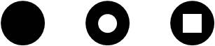
Standard aperture describes shape (circle, rectangle, Long circle, polygon) of aperture, size, painting part, and blank part to D code in AD parameter.
Special aperture associates AM (aperture macro) parameter to D code in AD parameter.
AM (aperture macro) parameter defines aperture shape, and size carries out numerical definition within AM parameter, or is set into variable modifier, and describes numerical value within AD parameter.
General AD parameter notation
%ADD<D-code number><aperture
type>,<modifier>[X<modifer>]*%
<D-code number>
D code number to define (10-999)
<aperture type>
Aperture description.
In the case of standard aperture, specify any one of (C, R, O, P, and T) as <aperture type>.
In the case of special aperture, describe aperture macro name defined as <aperture type> by AM parameter.
<modifier>[X<modifer>]
Be dependent on aperture type.
Divide plural <modifier> in text of X.
2.1. Definition after <aperture type> of standard aperture
| Aperture shape |
Definition after <aperture type> |
| Circle |
C,<outside diameter>[X<X-axis hole
dimension>[X<Y-axis hole dimension>]]
Put diameter of outside circle into <outside diameter>.
In order to define painting-out circle, input only diameter of outside circle.
When blank circle is in painting-out circle, put diameter of blank circle into the first <X-axis hole dimension>.
When blank rectangle is in painting-out circle, put width of blank rectangle into <X-axis hole dimension>, and put height of blank rectangle into <Y-axis hole dimension>.
The central point of outer circle and center of middle blank circle and rectangle are in accord.
Example of description:
%ADD10C,.05X0.025*%
Define circle aperture which has blank circle of diameter .025 in circle outside diameter 0.05 as D code 10.
|
| Rectangle |
R,<X-axis dimension>X<Y-axis
dimension>[X<X-axis hole dimension>X<Y-axis hole dimension>]

Put width of outside rectangle into <X-axis dimension>.
Put height of outside rectangle into <Y-axis dimension>.
If it is only painting-out rectangle, it is not necessary to put in parameter any more.
When putting blank circle into inside, put diameter of blank circle into <X-axis hole dimension>.
When putting blank rectangle into inside, width of blank rectangle is put into <X-axis hole dimension>, and it puts height of blank rectangle into <Y-axis hole dimension>.
The central point of outer rectangle and center of middle blank circle and rectangle are in accord.
Example of description:
%ADD22R,0.020X0.040*%
Define aperture of painting-out rectangle of width 0.02 and height 0.04 as D code 22.
|
| Long circle |
O,<X-axis dimension>X<Y-axis
dimension>[X<X-axis hole dimension>[X<Y-axis hole dimension>]]

Put width of outside Long circle into <X-axis dimension>.
Put height of outside Long circle into <Y-axis dimension>.
If it is only painting-out Long circle, it is not necessary to put in parameter any more.
When putting blank circle into inside, put diameter of blank circle into <X-axis hole dimension>.
When putting blank rectangle into inside, width of blank rectangle is put into <X-axis hole dimension>, and it puts height of blank rectangle into <Y-axis hole dimension>.
The central point of outer Long circle and center of middle blank circle and rectangle are in accord.
Example of description:
%ADD22O,0.020X0.04X0.005X0.010*%
Define Long circle aperture which has blank rectangle of width .005 and height 0.01 in Long circle outside width 0.02 and height 0.04 as D code 22.
|
| Regular polygon |
P,<outside dimension>X<number of
sides>[X<degrees of rotation>[X<X-axis hole
dimension>X<Y-axis hole dimension>]]
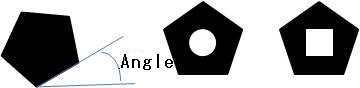
Put outside dimension into <outside dimension>.
Put the number of corners (3-12) into <number of sides>.
Put angle (degree) from the X-axis of the first direction into <degrees of rotation>.
If only painting-out regular polygon becomes, it is not necessary to put in parameter any more.
When putting blank circle into inside, put diameter of blank circle into <X-axis hole dimension>.
When putting blank rectangle into inside, width of blank rectangle is put into <X-axis hole dimension>, and it puts height of blank rectangle into <Y-axis hole dimension>.
Center of the central point of outer Long circle, middle blank circle, and rectangle is in accord.
Example of description:
%ADD17P,.030X4X0.0*%
Define regular polygon aperture which does not have blank into outside dimension .03, zero angle, and four corners as D code 17.
|
2.2.Definition after <aperture type> of special aperture
<aperture type>,<modifier>[X<modifer>]*%
<aperture type>
Describe aperture macro name with defined AM parameter.
<modifier> and after
Be dependent on aperture macro. Divide plural <modifier(s)> in text of X.
Example of description:
%ADD32DONUT,0.100X0X0X0.080*%
Define special aperture with defined aperture macro name DONUT of AM parameter as D code 32.
The size is 0.1, 0, 0, and 0.08.
3. AM parameter : definition of aperture macro
AM parameter is used in order to define aperture (call it special aperture) which had named.
Special aperture can make complicated-shaped aperture from putting many shape called primitive together in single aperture.
It is not necessary to set primitive with center of aperture.
AM parameter syntax rule
Like other parameters, begin in text of % and end in text of %.
Separate each primitive group by end-of-block character (usually *) within AM parameter block.
Divide modifier by comma within each primitive group.
modifier may put in 0, 1, 2, or numerical value like 9.05.
Within AM parameter, it may describe as variable modifier of $1-$n, and may describe value corresponding to it in AD parameter.
Within AM parameter, four operations and substitution can be performed between variable Modifier and numerical value.
Numbering $1 of AD parameter at the first variable, and numbering $2 of AD parameter at the 2nd variable etc. assign a number continuously from the left to the right.
When inputted instead of numerical value being variable modifier within AM parameter, variable modifier changes as follows.
For example, when numerical value is registered into the first variable, variable is set to $1 even if it is the 2nd primitive modifier.
Interpretation of each modifier changes with each primitives.
General notation of AM parameter
%AM<aperture macro name>*<primitive number>,<modifier$1>,<modifier$2>,[<...>]*[<primitive number>[<modifiers>]]*...*%
<aperture macro name>*
Aperture macro name quoted in AD parameter
<primitive number>
Primitive number identifies shape (circle, straight line, polygon, etc.).
<modifier$1>,<modifier$2>,<modifier$3>
Modifier differs in number and descriptive content by Primitive number.
Primitive of aperture macro
Primitive
number |
Shape |
Modifier |
| 1 |
Circle |
 |
$1 Exposure ON/OFF 0=OFF,
1=ON, 2=Reversed to the
present exposure
$2 Diameter
$3 Center X coordinates
$4 Center Y coordinates
|
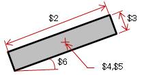
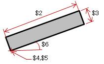
| 2 or 20 |
Straight line
(line segment designation) |
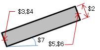 |
$1 Exposure ON/OFF 0=OFF,
1=ON, 2=Reversed to the
present exposure
$2 Line width
$3 Starting point X
coordinates
$4 Starting point Y
coordinates
$5 End point X coordinates
$6 End point Y coordinates
$7 Angle of rotation
|
| 21 |
Straight line
(Central point designation) |
 |
$1 Exposure ON/OFF 0=OFF,
1=ON, 2=Reversed to the
present exposure
$2 rectangle width
$3 rectangle height
$4 central-point X
coordinates
$5 central-point Y
coordinates
$6 angle of rotation
|
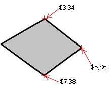
| 22 |
(Lower left point designation) |
 |
$1 Exposure ON/OFF 0=OFF,
1=ON, 2=Reversed to the
present exposure
$2 rectangle width
$3 rectangle height
$4 lower-left point X
coordinates
$5 lower-left point Y
coordinates
$6 angle of rotation
|
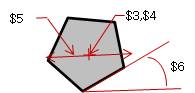
| 4 |
Polygon |
 |
$1 Exposure ON/OFF 0=OFF,
1=ON, 2=Reversed to the
present exposure
$2 The number of outside
corners
$3 Starting point X
coordinates
$4 Starting point Y
coordinates
$5 1st point X coordinates
$6 1st point Y coordinates
$7 2nd point X coordinates
$8 2nd point Y coordinates
It continues to maximum number 50.
$9 or the last number
Angle of rotation
|
| 5 |
Regular polygon |
 |
$1 Exposure ON/OFF 0=OFF,
1=ON, 2=Reversed to the
present exposure
$2 The number of polygon
corners
$3 Central point X
coordinates
$4 Central point Y
coordinates
$5 Diameter
$6 Angle of rotation
|
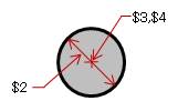
| 6 |
Moire |
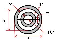 |
$1 Central point X
coordinates
$2 Central point Y
coordinates
$3 Outside diameter
$4 Circle line width
$5 Gap length of circle
$6 The number of circles
$7 Line width of cross line
$8 The length of cross line
$9 Angle of rotation
|
| 7 |
Thermal |
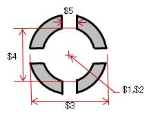 |
$1 Central point X
coordinates
$2 Central point Y
coordinates
$3 Outside diameter
$4 Inside diameter diameter
$5 Line width of cross line
$6 Angle of rotation
|
example 1:
%AMDONUT*1,1,$1,$2,$3*1,0,$4,$2,$3*%
Define aperture macro name DONUT containing two circles.
1,1,$1,$2,$3
Those values are described by circle (1), exposure on (1), diameter ($1), center X ($2), and center Y ($3) within AD parameter.
1,0,$4,$2,$3
Circle (1), Exposure off (0), diameter ($4, the first circle is differed from), Center X ($2) and Y ($3) use the same value as the first circle.
%ADD32DONUT,0.100X0X0X0.080*%
Define aperture macro name DONUT as D code 32.
$1 = 0.100
$2 = 0
$3 = 0
$4 = 0.080
Diameter ($1) of the first circle is 0.100.
Centers ($2, $3) of both circles are 0 and 0.
Diameter ($4) of the 2nd circle is 0.080.
example 2:
%AMDONUT*1,1,$1,$2,$3*$1=$2+0.030*1,0,$1-$4,$2,$3*%
Define aperture macro name DONUT which consists of two concentric circles.
Circle of the 1st diameter and circle of the 2nd diameter defined as a function of the center point are concentric circles.
1,1,$1,$2,$3
Circle (1), Exposure on (1), Diameter ($1) and Value of central point X and Y ($2, $3) are described within AD parameter.
$1=$2+0.030
Define variable used in order to calculate the 2nd diameter.
1,0,$1-$4,$2,$3
Circle (1), Exposure off (0), Diameter =$1-$4 and Central point X and Y ($2, $3, the same as the first circle).
%ADD33DONUT,0.020X0X0X0.014*%
Define aperture macro name DONUT as D code 33.
The 1st circle $1=0.020
$2=0
$3=0
The 2nd circle $1=$2+0.030
$4=0.014
Diameter ($1) of the first circle is 0.020.
Centers ($2, $3) of both of circles are 0 and 0.
Diameter of the 2nd circle is ($1-$4=$2+0.03-$4=0+0.030-0.014) =0.16.
example 3:
%AMDONUT*1,1,0.100X0X0*1,0,0.080X0X0*%
Define aperture macro name DONUT which consists of two concentric circles.
1,1,0.100X0X0
Circle (1), Exposure on (1), Diameter (0.100), Central point X and Y (0, 0)
1,0,0.080X0X0
Circle (1), Exposure off (0), Diameter (0.080), Central point X and Y (0, 0)
%ADD32DONUT*%
Define aperture macro name DONUT as D code 33.
Since AM parameter defines all values of modifier, there is no definition of value with AD parameter.
Return to Index
|
|
|
|
NC-Drill file to which PloView series supports
|
|
In printed wiring board designed by CAD, NC-drill file is used in order to make hole by NC drilling machine of Excellon.
When NC-drill file is read, it is converting to HP-GL/2 and displaying.
To format of Excellon, when there is little header section information, it can correspond by describing to configuration file.
Command with which PloView supports is as follows.
In addition, commands other than following are ignored.
; Comment
<<header section >>
M48 Header begins.
ICI, ON Relative coordinate mode
ICI, OFF Absolute coordinate mode
INCH, LZ Coordinates unit is inch. Omit leading zeroes of coordinate value.
INCH, TZ Coordinates unit is inch. Omit trailing zeroes of coordinate value.
METRIC[,{TZ|LZ}][,{000.000|000.00|0000.00}]
Coordinates unit is mm,
TZ: Omit trailing zeroes of coordinate
value
LZ: Omit leading zeroes of coordinate
value
000.000: More than decimal point
is triple digits + Within decimal point is triple digits
000.00 : More than decimal point is
triple digits + Within decimal point is double digits
0000.00: More than decimal point is
four digits + Within decimal point is double digits
[{ }] shows option selection.
| One of selections are shown.
T#C# It is setup of tool diameter to tool number.
M95 End of header
% End of header
<<body section >>
G05 Drill mode
G81 Drill mode
G90 Absolute coordinate mode
G91 Relative coordinate mode
G93X#Y# Zero set
M71 Coordinates unit is mm.
M72 Coordinates unit is inch.
T# Tool selection
R#X#Y# Hole is repeated and drilled by pitch X#Y# and number
of repetitions R#.
- When input file is not NC-drill file of Excellon designation format
When it is file with little header information to Excellon designation
format, it is necessary to describe to configuration file described below.
Return to Index |
|
|
| |
NC-Drill configuration file of PloView series products |
| |
The description method of DRILL parameter file is shown below.
- When letter of beginning of line is";", the line is comment line and nothing processes it.
- Please be sure to put line of "M48" which shows the beginning of program header into beginning of effective
line except for comment line.
- Specify coordinates unit as inch and specify "Omit trailing zeroes
of coordinate value" / "Omit leading zeroes of coordinate value".
As for the coordinate value, more than decimal point is two digit,
and under decimal point is four digits.
Example: 10.5 inches -- > 105000
General notation INCH[, {TZ or LZ}]
TZ :Omit trailing zeroes of coordinate value
Example: 15.0mm 001500 -- > 0015
LZ : Omit leading zeroes of coordinate value
Example: 15.0mm 001500 -- > 1500
[{ }] is option, or is either-selected.
Example: INCH, LZ
Omit leading zeroes of coordinate
value in inch specification
An omission uses INCH,LZ.
- Specify coordinates unit as mm, specify "Omit leading zeroes of
coordinate value" / "Omit trailing zeroes of coordinate value" and
"Upper decimal point number of digits" / "Under decimal
point number of digits".
General notation
METRIC[{TZ or LZ}] [and {000. 000 or 000.00 or 0000.00}]
TZ : Omit trailing zeroes of coordinate value
LZ : Omit leading zeroes of coordinate value
000.000: Upper decimal point is triple digits, under decimal
point is triple digits.
Example: 15.0mm -- >
015000
000.00 : Upper decimal point is triple digits, under decimal
point is double digits.
Example: 15.0mm -- >
01500
0000.00: Upper decimal point is four digits, under decimal
point is double digits.
Example: 15.0mm -- >
001500
[{}] is option. or is either-selected.
Example: METRIC, LZ, 000.00
It is mm specification, omit leading
zeroes of coordinate value,
upper decimal point is triple
digits, Under decimal point is double digits.
An omission uses METRIC,LZ,000.000.
- Absolute coordinate specification
General notation G90
- Relative coordinate specification
General notation G91
- Specification of diameter of tool to Tool number
General notation Tn [Cd]
n: Tool number (1-99)
d: Diameter of tool
[ ] is option.
Example: T12C1.1
Tool of diameter 1.1 of tool is
set to Tool number of No. 12.
- Be sure to put in the line of "M95" indicating the end of the
program header at the end.
Please refer to following Excellon company H.P. for details.
Excellon Format
Return to Index |
| |
|
| |
IGES file to which PloView series supports |
| |
IGES file is format upon which ANSI decided, and is middle format at time
of carrying out data exchange between different CADs.
1.Reading
When the file is read, it is converted to HP-GL/2 and displayed.
Figure which can read PloView, and figure which cannot be read are shown below.
| |
Type, figure |
Type, figure
which can be read |
100:Circular arc
102:Composite Curve
104:Conic arc
106:Point array
110:Lin
112:Parametric spline curve
114:Parametric spline surface
116:Point
118:Ruled Surface
120:Surface of Revolution
122:Tabulated Cylinder
124:Transformation matrix
126:Rational B-spline Curve
128:Rational B-spline surface
142:Curve on a parametric surface
144:Trimmed surface
202:Angular dimension
206:Diameter demension
208:Flag note
210:General lavel
212:Text, General Note
214:Leader (arrow)
216:Linear dimension
218:Ordinate dimension
220:Point dimension
222:Radious dimension
228:General Symbol
230:Section area
308:Subfigure definition
402:Associative instance
404:Drawing
408:Singular subfigure instance |
Type, figure
which can not be read |
108:Plane
125:Flash
130:Offset curve
132:Connect point
140:Offset Surface
141:Boundary
143:Boundary Surface
312:Text template
314:Color Definition
320:Network subfigure definition
406:Property
410:View
412:Rectangular Array Subfigure Instance
414:Circular Array subfigure instance
416:External Reference
418:Nodal Load/Constraint
420:Network subfigure instance
422:Attribute Table Instance
430:Solid Instance
502:Vertex
504:Edge
508:Loop
510:Face
514:Shell |
2.Output
Relation HPGL-Pen:IGES-Pen:
There are only IGES 's pens from 1 to 8 pens, and the color for the pen
number is decided as follows.
| IGES Pen No. |
Color |
| 1 |
Black |
| 2 |
Red |
| 3 |
Green |
| 4 |
Blue |
| 5 |
Yellow |
| 6 |
Magenta |
| 7 |
Cyanogen |
| 8 |
White |
Therefore, PloView performs color control by assigning IGES pen number
from HPGL pen number. If the pen number of HPGL is 9 or more is used, IGES's
pen number is 1 to 8 by doing the following processing.
IGES pen number = ((HPGL pen number -1) MOD 8) +1
Text font:
Depending on the contents set with "Set" "Text" and character string.
If Vector Font is selected and the character string is an ASCII single byte character, or in Japanese, the Vector Font of PloView series products is used, and in IGES file it is converted to line segment data.
If Windows Font is selected and the character string is ASCII single-byte character, or in Japanese, it is converted to IGES notation.
Figure which can be outputted:
Inside of table "-" means "not outputting".
| |
Type |
Figure |
| Line |
110 |
Line |
| Polyline |
106 |
Point array |
| Circle |
100 |
Circular arc |
| Arc |
100 |
Circular arc |
| Text of Vector Font |
110 |
Line |
| Text of Windows Font |
212 |
Text, General Note |
| Hatcting |
110 |
Line |
| Painting out |
110 |
Line |
| Image |
- |
- |
| PC,PW |
- |
- |
Return to Index |
| |
|
| |
SXF file to which PloView series supports |
| |
CAD data exchange standard consortium (SCADEC) which is initiative of the Ministry of Land, Infrastructure and Transport of Japan, and was established in March, 1999 developed SXF. SXF is intermediate-file format used when exchanging data between different CAD.
It is the abbreviation for Scadec data eXchange Format. In Japan, it is handled as a standard file in electronic delivery of drawing.
SXF format are two kinds, SFC (feature comment file) and P21 (STEP file).
P21 is format based on STEP/AP202 accepted internationally and extension
of file name is ".p21".
SFC is easy handling for conversion time to be short etc. because file
size is small compared with P21, but it is format unique to Japan, it is
format accepted only in Japan.
Extension of SFC file name is ".sfc".
When file is read, PloView is converted into HP-GL/2+HP-RTL and displayed.
Layer of SXF is converted into page in Ploview series.
[About copyright]
PloView series uses "SXF common library Ver.3.xx" for SXF file
input-and-output function.
Copyright of "SXF common library Ver.3.xx" belongs to Information-technology Promotion Agency, the Ministry of Land, Infrastructure and Transport, JACIC, and OCF.
Return to Index |
| |
|
| |
Drawing area when reading files of PloView series products |
| |
The area displayed when the Diaplay all command is issued is the drawing area.
There is usually no problem if you select "Figure maximum area".
However, when multiple drawings are stacked to form a single product, such as a printed wiring board, the alignment between the drawings is important, so the drawing areas of each drawing must match.
1. HPGL file
HPGL files do not contain information about drawing area.
The machine origin of the HPGL plotter may be lower left or center of the graphic limit (area determined by the area where mechanical drawing is possible, size of paper, soft clip area, etc.) depending on the plotter model. Draw according to the HPGL data as the origin (0, 0) of the dimensional coordinate system.
When the machine origin of the HPGL plotter is at the lower left, the lower left of the drawing area is the origin (0.0) of the HPGL data.
However, when the machine origin of the HPGL plotter is at the center, the graphic limit of the plotter fluctuates on a case-by-case basis and can not be determined uniquely.
The upper right corner of the drawing area can not be obtained from the HPGL data.
Select the "Set" "Input File" menu, and use the "Drawing
Area" radio button to select how to find the drawing area.
- Figure maximum area ... default
Make the largest area of the figure contained in the HPGL file the drawing area.
In the case of HPGL file that contains drawing frame figures that correspond to drawing areas, selecting this item can reflect the drawing area.
The HPGL file, in which PloView and PloComp output the entire drawing, contains data to be moved with pen-up at the lower left and upper right points of the drawing area. Therefore, if this item is selected when importing this HPGL file, the original drawing area can be reflected.
- PS (PlotSize) instruction area
If there is a PS (PlotSize) instruction in the HPGL file, set the lower left of the drawing area as the origin (0, 0) and the upper right as the length and width of the PS instruction.
If there is no PS instruction in the HPGL file, the drawing area will be the figure maximum area.
- IW (Input Window) instruction area
If there is IW (Input Window) instruction in the HPGL file, the drawing area will be the area of the IW instruction.
If there are multiple IW instructions, the area of the last IW instruction is used.
If there is no IW instruction in the HPGL file, the drawing area will be the figure maximum area.
- IP (ScalePoint) instruction area
If there is IP (ScalePoint) instruction in the HPGL file, make the drawing area the area of the IP instruction.
If there are multiple IP instructions, the area of the last IP instruction is used.
If there is no IP instruction in the HPGL file, the drawing area will be the figure maximum area.
- Automatic (PS-> IW-> IP-> Figure maximum area)
If there is PS (PlotSize) instruction in the HPGL file, set the lower left of the drawing area as the origin (0, 0) and the upper right as the length and width of the PS instruction.
If there is no PS instruction,
If there is IW (Input Window) instruction in the HPGL file, the drawing area is made the area of the last IW instruction.
If there is no IW instruction,
If there is IP (ScalePoint) instruction in the HPGL file, make the drawing area the area of the last IP instruction.
If there is no IP instruction,
Makes the drawing area the largest figure area.
Note: When setting other than default, if the HPGL file contains information
different from drawing area information in the parameters of PS (PlotSize),
IW (InputWindow), and IP (ScalePoint), it becomes an abnormal drawing area.
"Include origin in drawing area":
If this is checked, the HPGL file origin will be included in the drawing area.
Valid for setting the lower left of the drawing area when the machine origin of the HPGL plotter is lower left of the graphics limit.
If this check is removed, the contents will be ignored.
2. How to obtain drawing area other than HPGL file
- PDF, EMF, DXF, DWG, Image file such as TIFF, SXF: File drawing area information
- IGES, Gerber, NC-Drill: Maximum area of figure
Return to Index |
| |
|
|
Contact us
|
|

Return to Index |
|